Get in touch with FlexBlanket Company

Silicone Rubber Heaters
Custom Silicone Rubber Heaters for Industrial Equipment
FlexBlanket Industrial Flexible Heating
We build fiberglass-reinforced silicone rubber heaters around your heated surface, electrical supply, control method and installation envelope. Start with the object, temperature target and available contact area; the heater configuration follows those inputs.
- 0.8–3.0 mm thickness
- -60°C to 250°C temperature
- 12-230V AC/DC supply
- Custom shapes & cutouts

Silicone Rubber Heaters at a Glance
Configuration gate
Using a family value without the actual heat sink creates hot-spot risk; request a detailed custom review.
Family range versus configured rating
Applying the 1.0–3.0 W/cm² family range without the actual heat sink, contact area and control method creates hot-spot risk.
Request a custom engineering reviewwith a detailed surface drawing before treating any value as a released specification.
Custom Geometry, Cutouts, Voltage and Wattage Configuration
A silicone rubber heater manufacturer must start custom silicone heaters on the usable contact area, not the outside dimensions. Openings, unsupported edges, lead exits and changing heat sinks all alter the heating circuit and temperature profile.
Geometry map
Provide dimensions, shapes, cutouts, voltage, wattage and mounting method. Mark the heated zone separately from clearances, holes and clamp lands.
Electrical inputs
State the available supply, total wattage limit, switching method and connector boundary. FlexBlanket supports 12 VDC, 24 VDC, 48 VDC, 120 VAC, 230 VAC and custom voltage configurations.
Control inputs
Specify the sensing point and whether the assembly needs a thermostat, RTD, thermocouple and PID temperature control. Place the sensor where it represents the temperature you intend to control.
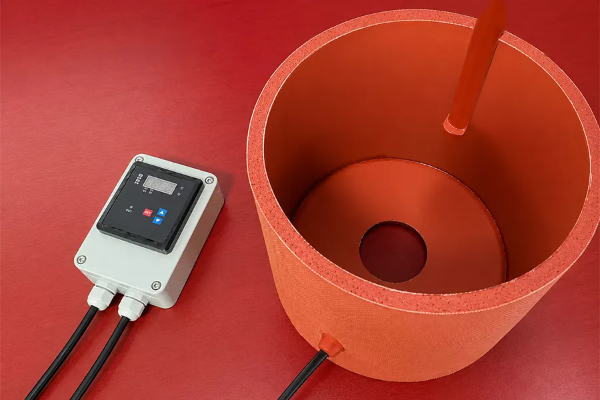
RFQ variables that change the design
| Input | What it controls | Missing-input risk |
|---|---|---|
| Heated object and drawing | Heater size and shape | Contact area may be assumed incorrectly |
| Cutouts and edge clearances | Circuit path and local heat pattern | Cold zones or hot edges can appear |
| Voltage and available current | Electrical resistance and lead arrangement | The circuit may not match the supply |
| Target, starting and ambient temperature | Required heat input and control window | A nominal wattage can miss the process target |
| Sensor and controller | Feedback point and switching behavior | The controller can regulate the wrong location |
Fiberglass-Reinforced Silicone Rubber Operating Envelope
Flexible silicone construction supports thin surface heating on flat, curved and irregular equipment. FlexBlanket lists resistance to ozone, acids, alkalis and moisture; material compatibility still depends on concentration, exposure time, temperature and the complete assembly.
Mechanical fit
- Thin profile where a rigid heater does not fit
- Flat sheets, formed sleeves and wrapped heater forms
- Custom openings around ports, fasteners and service features
- Lead routing set from the installation drawing
Environmental inputs
- Ambient and process temperature
- Moisture, washdown and dust exposure
- Acid, alkali, ozone or other chemical contact
- Abrasion, vibration and handling during service
Operating-envelope screen
| Condition | Relevant product fact | RFQ decision |
|---|---|---|
| Low-temperature start | -60°C lower value in the product file | State the cold-start ambient and required warm-up target |
| High-temperature surface | 250°C upper value in the product file | Define surface, lead-exit and control temperatures separately |
| Wet or dusty area | Dustproof and waterproof configurations are available | Name the exposed components and required enclosure boundary |
| Chemical exposure | Silicone material resistance is listed for ozone, acids and alkalis | Provide chemical, concentration, contact mode and cleaning cycle |
SYS_CMD
Temperature is an application result
FREek publishes surface temperature against an explicit test setup and lists watt density, heated mass, conductivity, mounting, ambient and airflow as variables. Do not treat the -60°C to 250°C family range as an installed-surface guarantee.
Surface Interface and Mounting Requirements
Heat transfer requires intimate contact between the flexible heater and the substrate. A clean, smooth and burr-free surface minimizes puncture and abrasion risk, while trapped air creates an insulating gap that can turn into a local hot spot.
Product-File Ratings and the Test Context Your RFQ Must Define
These values describe the FlexBlanket silicone rubber heater family. A quote must define geometry, mounting, measurement conditions and the components included in the tested assembly.
| Specification | Product-file rating | Decision boundary |
|---|---|---|
| Construction | Fiberglass-reinforced silicone rubber | Product-family construction |
| Thickness | 0.8–3.0 mm | Final build follows geometry and configuration |
| Voltage | 12/24/48 VDC; 120/230 VAC; custom | State nominal supply and switching method |
| Power density | 1.0–3.0 W/cm² | Engineering selection follows heat loss, substrate, contact and control |
| Operating temperature | -60°C to 250°C | Separate heater surface, lead exit, connector and process targets |
| Temperature uniformity | ±5°C | Define heated area, substrate, mounting, ambient, soak time and sensor map |
| Insulation resistance | ≥300 MΩ | Define test voltage, electrode arrangement, conditioning and finished-heater scope |
| Dielectric strength | ≥2500 V | Define AC or DC, frequency, duration and specimen or assembly scope |
| Protection rating | IP65 | Quote must identify heater body, edge seal, lead exit, connector and controller coverage |
| Temperature control | Thermostat, RTD, thermocouple, PID | Confirm sensor type, location, setpoint range and switching load |
Evaluation Process
Electrical relationship check
Calculate nominal current and resistance from buyer-entered voltage and wattage. Treat the result as an arithmetic check, not a heater selection.
Evaluation Process
Compare physical heater forms
Compare flat, formed, wrap and jacket formats against contact, removal and control inputs.
Price and Build-Schedule Inputs for a Custom Heater
Cost correlates with heated surface, geometry, cutouts, electrical load, controls, leads, mounting, quantity and documentation. Schedule correlates with the same design-review cycle plus material availability and approval of the configuration.
Cost and schedule drivers
RFQ readiness
A price and schedule can be confirmed after the application, geometry, electrical load, control boundary and quantity are reviewed together. Submit those fields once; avoid a quote based on an assumed mounting surface or connector.
Build the Input Record
Start My Heater RFQ
Electrical Protection and Temperature-Control Boundaries
Factory review considers the heater body, lead exit, connector, controller and installed machine as separate verification objects. Determine which pieces belong to the quoted assembly before an electrical value or IP code is used as an acceptance criterion.
Electrical acceptance fields
- Nominal voltage and total wattage
- Insulation-resistance test voltage and conditioning
- Dielectric-test waveform and duration
- Protective earth or bonding requirement
- Connector, cable and controller scope
Thermal acceptance fields
- Target surface and process temperature
- Sensor type and physical location
- Controller and switching behavior
- Ambient, airflow and insulation
- Warm-up, soak and measurement points
IP65 scope under IEC 60529
IEC 60529 applies an IP code to the enclosure or assembly evaluated for dust and liquid ingress. Define the desired boundary in the RFQ so the quote can specify whether it applies to the heater body alone or also the edge seal, lead exit, connector and controller.
Engineering review rule // Critical
An IP65 label on the heater body is not a substitute for an assembly-level boundary, because an uncovered lead exit or connector can invalidate the intended ingress-protection scope. FlexBlanket resolves that risk by binding the heater body, edge seal, lead exit, connector and controller to the quotation; IEC 60529 supplies the code framework.
Uniform heat needs a defined measurement plane
FlexBlanket’s product file lists ±5°C uniformity, but a cutout, exposed edge, uneven clamp or distant sensor can change the installed temperature map. Name the measurement surface, load state, soak time and sensor positions in the acceptance plan.
DEFINE RFQ BOUNDARYThe Application-Input-to-Engineering-Review Path
01
Define the heated object.
Provide the drawing, substrate, contact area and installation limitations.
02
Establish the thermal duty.
Declare starting, target and ambient temperatures, airflow, insulation and desired warm-up profile.
03
Define the electrical boundary.
Declare voltage, available current, switching method, sensor and controller.
04
Specify the heater.
Identify cutouts, clearances, lead exit, connector position and any unsupported region.
05
Examine the assembly.
FlexBlanket engineering reviews geometry, power density, contact, control and exposed components as a single system.
06
Verify the quote basis.
A formal quote documents the approved configuration, quantity and acceptance criteria.
Silicone Heater RFQ Decision Matrix
| Buyer input | Decision it unlocks | Risk when omitted |
|---|---|---|
| Heated object and contact area | Heater outline and heat-transfer path | The electrical load may be based on the wrong sink |
| Dimensions, holes and cutouts | Circuit path and edge clearance | Heat can be concentrated beside an opening |
| Target, start and ambient temperatures | Thermal duty and control range | The heater may reach temperature too slowly or overshoot |
| Voltage, current limit and wattage | Resistance and wiring arrangement | The circuit may exceed the available supply |
| Sensor type and location | Control feedback point | The controller may regulate a cooler or hotter spot than the process |
| Mounting and insulation | Contact quality and outward heat loss | Voids can cause hot spots and lost heat |
| Lead exit and connector | Strain relief, routing and enclosure boundary | The heater can fit while the termination does not |
| Environment and cleaning | Material and ingress-protection review | The stated body rating may not cover the exposed assembly |
| Quantity and destination | Build planning and document review | The quote may omit a market-specific requirement |
Documented Heater Forms for Pipes, Valves, Cylinders and Equipment
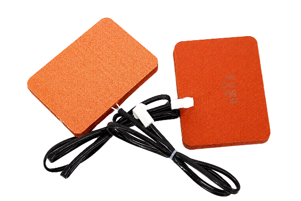
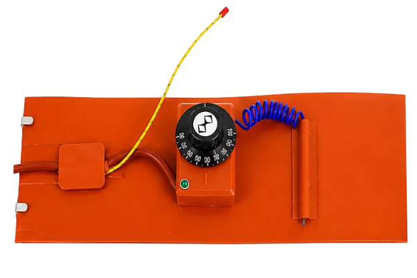
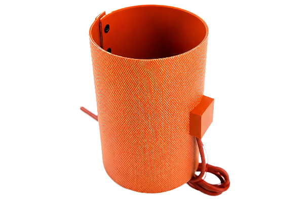
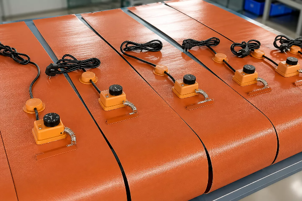
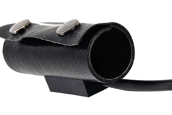
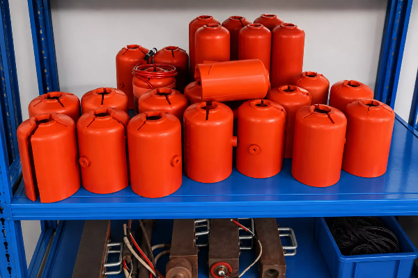
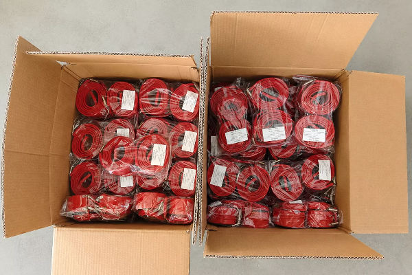
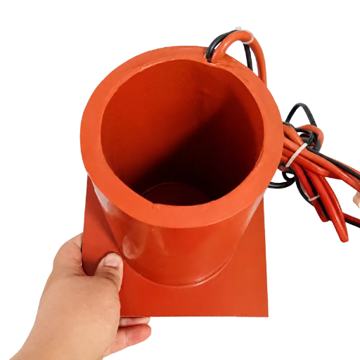
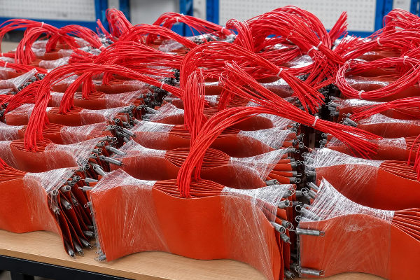
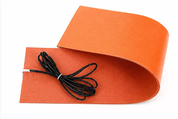
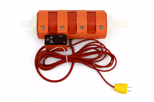
Client-supplied product images show flat silicone heating pads, silicone blanket heater formats, formed sleeves, wrapped assemblies and equipment-specific shapes. These forms are not interchangeable; each shape alters contact, removal and lead-routing considerations. These images show physical formats; they are not presented as named customer cases or installed-performance evidence.
Flat flexible heater mat for direct surface contact.
Flat flexible heater mat for direct surface contact.
Formed heater body for a cylindrical equipment surface.
Equipment-specific formed heater with integrated lead routing.

Removable heater assembly around an inline component.
Batch heater assemblies with repeated lead and fastening details.
Product forms in the FlexBlanket range
-
Flat heaters
Thin pad and mat formats for plates, tanks and equipment surfaces.
-
Pipe wraps
Wrapped formats for straight pipe, hose and cylindrical heat paths.
-
Valve heaters
Shaped coverage around bodies, ports and service clearances.
-
Insulated jackets
Flexible heating with an insulation layer where outward heat loss must be reduced.
-
Cylinder heaters
Formed contact for round vessels and equipment bodies.
-
FlexBlanket supplies flat heaters, insulated jackets, valve heaters, pipe wraps, cylinder heaters and equipment-specific formed heaters.
SPECIFICATIONS
Silicone Rubber Heater Fit Limits and Alternative Routes
A flexible silicone heater is most capable when it can transfer heat into a defined surface under predictable contact. It is the wrong choice when the temperature, interface or control boundary exceeds that model.
Silicone Rubber Heater Engineering Tools
Access our engineering resources to specify requirements, calculate electrical parameters, and compare optimal heating formats for your industrial application.
-
Application Input Record
Document your specific thermal requirements, dimensions, and operational environment to streamline custom heater engineering.
Use Tool -
Electrical Relationship Calculator
Instantly calculate voltage, wattage, and resistance metrics to ensure the optimal electrical configuration for your heating system.
Use Tool -
Heater Form Comparison
Compare different silicone rubber heater forms, formats, and structural specifications to select the ideal setup for your equipment.
Use Tool
Send Your Silicone Heater Application Inputs
Open the Blocksy RFQ popup with the heated object, drawing and electrical boundary ready. Submitting these inputs starts engineering review; it is not an accepted heater specification.
Unvalidated — engineering review required
-
01
Heated object
Material, wall thickness and contact area
-
02
Geometry
Dimensions, cutouts, clearances and bend direction
-
03
Thermal duty
Starting, target and ambient temperatures
-
04
Electrical duty
Voltage, wattage limit and switching method
-
05
Control
Sensor, location, setpoint and controller
-
06
Interface
Mounting, insulation, lead exit and connector
-
07
Environment
Moisture, dust, chemicals, vibration and cleaning
-
08
Procurement
Prototype quantity, order quantity and destination
Electrical resistance inside the silicone heating element produces heat, and the flexible body conducts it into the contacted surface. Contact area, substrate conductivity, insulation and airflow determine how much of that heat reaches the process.
Begin with the supply available at the installation. Available options include 12 VDC, 24 VDC, 48 VDC, 120V AC, 230 VAC and custom configurations. Bind voltage, wattage, switching hardware, connector and controller supply in the quote so procurement compares one electrical boundary.
The available range is 1.0–3.0 W/cm². Select within it only after reviewing heat loss, heated mass, substrate conductivity, contact, ambient conditions and control.
State sensor type, location, setpoint range, switching load and assembly boundary.
Custom dimensions, shapes and cutouts are available in flat, formed and wrapped heater bodies. Define the three-dimensional contact surface, bend direction, minimum edge clearance, cutout coordinates and lead route on the drawing. A mating-part model or dimensioned section helps engineering distinguish a flexible wrap from a factory-formed assembly.
IEC 60529 assigns an IP code to the enclosure or assembly tested. Require the quotation to identify the exact IP65 boundary.
Show outside profile, heated zone, cutouts, keep-outs, bend lines, lead exit side, connector space and attachment points. Mark the substrate, allowable unheated border and contact area. Add the permitted lead direction, strain-relief envelope and any nearby obstruction so the approved drawing governs installation clearance.
Heated area, thickness, cutouts, voltage and total wattage define the heater body. Sensor type, controller, lead construction, connector, mounting system and document scope define the supplied assembly. Quantity, prototype validation and destination requirements then determine which engineering and production work belongs in the quotation, so submit one application record for each configuration.
Geometry approval, electrical design, control components, quantity and buyer review timing set the build path.
Name the destination country, final equipment type, supply voltage and installation environment. List the declarations, reports, labels or traceability records required by your approval route, including the exact standard edition when known. Compliance scope follows the quoted heater, lead exit, connector and controller configuration; evidence for another model or a raw silicone material does not establish assembly compliance.