Get in touch with FlexBlanket Company

Updated August 2026
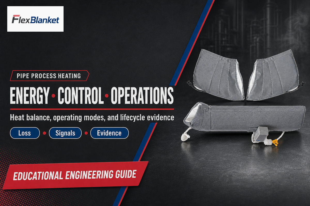
Pipe Process Heating is the controlled delivery of heat to a piping system so a process fluid stays inside a required operating window. System duty belongs to the complete assembly, fluid, pipe, insulation, heater, power or steam supply, sensors, controls, alarms, and operating procedure, not to one heater model.
Direct answer
Pipe process heating succeeds when heat input covers condition-specific losses and process load while the control system measures the right temperature object. Power alone can’t prove fluid temperature, accessible-surface safety, stable operation, or a safe restart after maintenance.
Quick operating brief
| Primary reader task | Define heat, signal, operating-mode, and evidence requirements. |
|---|---|
| Four temperature objects | Heater, pipe wall, process fluid, and employee-accessible outer surface. |
| Evidence basis | Government, university, peer-reviewed, and standards-organization sources. |
| Not supplied here | Project wattage, setpoints, site classification, product approval, or a quotation. |
Key points
- Heat-loss and warm-up calculations answer different questions.
- Controller displays don’t automatically represent fluid temperature or touch risk.
- Startup, normal operation, shutdown, and recovery need different evidence.
- Ordinary resistance trace heating and explosive-atmosphere work don’t share one standards path.
Define the Operating Boundary Before Adding Heat
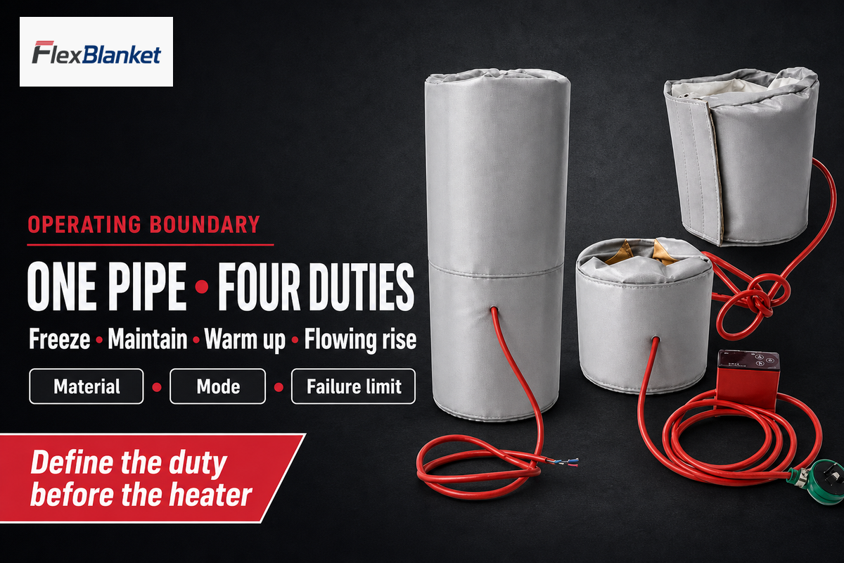
With the complete system scope established, pipe process heating begins with an operating boundary: what material is moving, which temperature must be maintained, how the line behaves during no-flow periods, and what failure must be prevented. That boundary separates freeze protection, temperature maintenance, controlled warm-up, and a deliberate temperature rise across a flowing process.
U.S. Department of Energy process-heat guidance places the material and heat source inside one system. That framing matters for pipes because a warm pipe wall is not the same outcome as a fluid that reaches the required viscosity, reaction limit, or delivery temperature.
| Duty | Question answered | Primary evidence | Limitation |
|---|---|---|---|
| Freeze protection | Can the vulnerable section remain above its freeze or solidification boundary? | Lowest ambient, no-flow duration, line contents, insulation state | Does not prove normal process temperature |
| Temperature maintenance | Can heat input replace steady loss while material moves or waits? | Loss per length, operating hours, flow/no-flow modes | Setpoint alone does not prove fluid uniformity |
| Controlled warm-up | Can the system raise stored thermal mass within an allowed time and rate? | Mass, heat capacity, temperature change, losses, phase terms | Requires a transient calculation |
| Flowing-process rise | Can the fluid gain the required energy between inlet and outlet? | Mass flow, inlet/outlet targets, heat capacity, residence time | Wall heating does not guarantee outlet condition |
Before a heated chemical is treated as suitable, review its current Safety Data Sheet. OSHA’s mandatory format separates handling and storage, physical properties, and stability and reactivity. Those sections are inputs to an engineering review; they are not an automatic permission to heat the material.
A search such as “pipe heater for PVC” raises a material-temperature compatibility question before it raises a heater-selection question. Verify the actual pipe material, pressure and temperature limits, contents, joining method, and upset condition instead of applying a generic search label to the design basis.
What Are the Different Kinds of Process Heating Systems?
Process-heating categories describe energy paths, not a universal shopping list. Department of Energy guidance uses three broad categories—fuel-fired, steam-based, and electric—while industrial pipe applications also use method-specific arrangements such as resistance tracing, surface heaters, impedance, induction, and direct-pipeline heating.
Translate each method into four control questions: What variable can be adjusted? How quickly does heat reach the controlled object? Which independent limit prevents harm? What evidence proves the transition worked? IEC/IEEE 62395 evidence in this guide applies only to electrical resistance trace heating. Induction, impedance, skin-effect, and direct-pipeline methods need their own evidence.
Terminology and Adjacent-Intent Boundary
Mixed search results use overlapping heat language for different equipment and physical mechanisms. The map below organizes those terms without treating every phrase as a pipe-heating method, performance claim, or product recommendation.
| Language group | Engineering interpretation | Boundary for this guide |
|---|---|---|
| System families | Industrial process heating systems may use process heaters, a boiler, or an electric process heating arrangement. Process heating systems include many heating applications and process heating applications; a heating element, electric heating elements, electric heaters, direct heating, and resistive heating name only some options. | Method words do not select equipment or establish suitability. |
| Energy path | State where heat is generated, how heat generated at a heat source becomes heat supplied or heat input, and whether heat is applied as heat directly from the source. A defensible use of heat or application of heat also names the heating mechanisms and contact with the material. | Using heat is not proof that the required process condition was reached. |
| Thermal state | High temperature, low temperature, lower temperature, temperature range, temperature difference, latent heat, and level of heat refer to different variables or conditions. High thermal properties and heat produced still need units, locations, and test conditions. | One adjective or temperature value cannot define the full duty. |
| Transfer medium | A heat transfer fluid, vapor, conductive path, or other thermal systems can transfer heat between two locations. A device filled with a working fluid may rely on a small amount of liquid, while heat in the process pipe follows the actual geometry and operating mode. | These mechanisms require separate calculations and evidence. |
| Energy performance | Waste heat, recovering heat, heat away to a heat sink, and efforts to minimize heat loss affect the amount of energy and efficiency of the system. Efficient heat delivery may be cost effective only after hours, utility losses, control behavior, and tariff are known. | No universal savings percentage follows from the terminology. |
| System design | In process heating today, system design defines how systems operate, systems consist of interacting parts, and systems allow specific transitions. Engineers design the system for various industrial conditions rather than from one search phrase. | Design remains project-specific and version-controlled. |
| Adjacent equipment | A heat exchanger, water heating equipment, water heaters, process air systems, solar heating, and heating and cooling systems may share thermal vocabulary with pipe heating. | Shared words do not make those technologies equivalent to controlled pipe process heating. |
| Operating judgment | Heat generation, available heat capacity, specific heat, and the heat transfer path must be connected to a current operating mode, material state, and evidence owner. | A term match is an input prompt, not an engineering answer. |
In this map, heat from the source means net energy crossing the defined system boundary, not the source’s nameplate input.
For physical blanket-versus-cable selection and installation, use the existing pipe heating blanket selection and installation guide. Keeping that decision on its current page prevents this operating guide from becoming a second product selector.
Build the Heat Balance From Loss and Warm-Up Loads
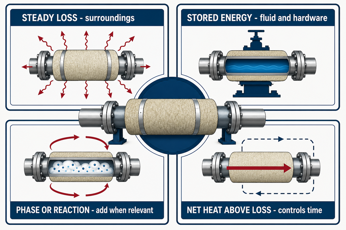
A pipe heat balance must keep three loads separate: steady loss to the surroundings, energy stored in the fluid and hardware during warm-up, and any process term such as phase change or reaction. Combining them into one watts-per-length rule hides the operating mode and makes the result difficult to verify.
Oak Ridge National Laboratory’s MEASUR insulated-pipe documentation models pipe geometry, insulation, temperatures, convection, radiation, length, operating hours, and efficiency. Its iterative surface-temperature method is evidence that pipe loss is condition-bound, not a promise that one catalogue wattage fits every line.
Load–Loss–Control Ledger
Load–Loss–Control Ledger fields keep project inputs, calculated loads, supplied heat, and the controlled variable in one reviewable record.
| Field | Value and unit | Owner | Evidence | Limitation |
|---|---|---|---|---|
| Operating mode | freeze / maintain / warm-up / flowing rise | Process | Approved design basis | Modes cannot share assumptions silently |
| Material identity | name, composition, phase | Process/EHS | Current SDS and process data | Supplier trade name is insufficient |
| Allowed temperature window | minimum and maximum, °C | Process/EHS | Qualified material/process limit | Not the heater’s catalogue maximum |
| Pipe geometry | diameter, length, fittings, m | Mechanical | Current drawing and walkdown | Supports and valves change the heat path |
| Insulation state | material, thickness, condition, mm | Mechanical/Maintenance | Specification plus dated inspection | Nominal thickness does not prove current condition |
| Ambient exposure | temperature, wind, indoor/outdoor | Process/Mechanical | Site design basis | One weather value may miss the worst mode |
| Steady loss | W/m and total kW | Thermal design | Calculation revision | Valid only for its input set |
| Warm-up load | kJ or kWh per event | Thermal design | Mass × Cp × ΔT plus added terms | Must include hardware and phase/reaction terms when relevant |
| Available heat input | kW, steam flow, or method-specific input | Electrical/Utilities | Approved equipment and utility data | Nameplate input is not net heat to fluid |
| Control object | heater / wall / fluid / outer surface | Controls/Process/EHS | Loop narrative and test record | One object cannot prove the others |
Worked warm-up example with replaceable inputs
Assume an illustrative 20 kg fluid inventory with a specific heat of 2.0 kJ/kg·K must rise by 30 K. Sensible energy is 20 × 2.0 × 30 = 1,200 kJ, or 0.333 kWh. If verified net heat above concurrent loss is 2.0 kW, the fluid-only ideal time is 0.333 ÷ 2.0 = 0.167 hours, about 10 minutes.
That 10-minute result isn’t a design time. It excludes the pipe and insulation thermal mass, changing heat loss, imperfect heat transfer, mixing, flow, controller cycling, phase change, reaction, and safety limits. Add those terms before using the calculation. For project inputs, the site’s duty and delta T worksheet provides a structured handoff.
Before calculation, test whether the worksheet keeps units and conditions together. The following values are illustrative and replaceable; their purpose is to keep each number attached to its unit, operating mode, and evidence source.
| Input type | Illustrative value | Condition to retain |
|---|---|---|
| Segment length | 30 m | drawing revision and included fittings |
| Outside diameter | 114.3 mm | actual pipe and coating |
| Insulation thickness | 50 mm | material and dated condition |
| Ambient | −10 °C | selected operating case |
| Maintenance target | 40 °C | named temperature object |
| Wind | 5 m/s | exposure basis |
| Mass flow | 500 kg/h | fluid state and mode |
| Available input | 3 kW | approved equipment state |
| Circuit voltage | 230 V | supply and circuit identity |
| Measured current | 13 A | test method and timestamp |
| Protective setting | 16 A | approved circuit design |
| Supply frequency | 50 Hz | site utility |
| Validation hold | 60 min | approved acceptance plan |
| Formal review interval | 12 months | site procedure and change triggers |
A separate illustrative check could model a 24 hr standby interval and require a condition review after 7 days of abnormal exposure. These time values are placeholders, not operating instructions.
Track Insulation Condition as a Changing Heat-Loss Input
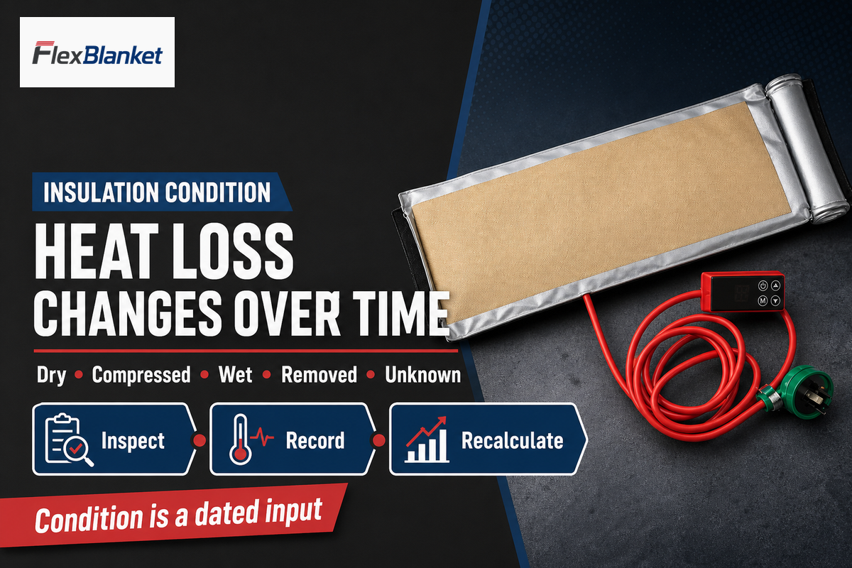
Insulation is a dated operating input, not a permanent label. Thickness, conductivity, compression, moisture, open joints, damaged weather barriers, and removed sections can change surface temperature and heat loss after the original calculation. A maintenance event can therefore invalidate an earlier energy model without changing the heater.
ORNL’s insulated-pipe method distinguishes insulated and bare pipe and iterates the outer-surface condition. That logic supports a practical rule: tie every heat-loss calculation to an inspection date and insulation state. Don’t assume the purchase specification still describes the line after access, water ingress, or repair.
| Observed state | Model action | Operating evidence | Limitation |
|---|---|---|---|
| Dry and intact | Use verified material and thickness | Dated inspection and specification | Still verify joints and supports |
| Compressed | Recheck effective thickness and contact | Walkdown record | Nominal thickness may overstate resistance |
| Wet or water-damaged | Treat prior loss value as suspect | Repair and dry-out record | Visual appearance may not show internal moisture |
| Section removed | Model the local discontinuity | Access permit and reinstatement check | Short gaps can create local cold or hot regions |
| Condition unknown | Do not reuse the old result as verified | Inspection required | Uncertainty must remain visible |
This section deliberately stops before physical blanket fit, overlap, sensor placement, or seasonal inspection. Those implementation tasks remain on the existing blanket guide, which protects both reader clarity and keyword ownership.
Separate Heater, Pipe-Wall, Fluid, and Accessible-Surface Temperatures
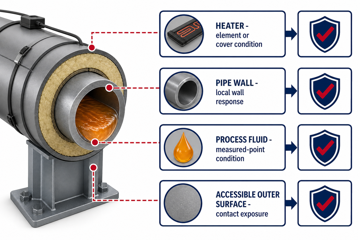
After insulation and installation scope are separated, four temperatures can coexist in one pipe-heating system: the heater, the pipe wall, the process fluid, and the employee-accessible outer surface. Each answers a different control or safety question. A reading is evidence only for the location and response represented by its sensor and test method.
For liquid service, temperature control begins by naming which of those four objects the loop is intended to represent and which independent limit protects the others.
One peer-reviewed temperature-feedback study treats the heater, feedback measurement, and controlled object as coupled but distinct. Because its geometry is not industrial piping, no sensor position or accuracy value transfers. Only the feedback-objective principle carries into this guide.
4-Object Temperature Evidence Map
| Object | What it can show | What it cannot show alone | Next evidence |
|---|---|---|---|
| Heater | Element or cover condition relative to its limit | Fluid temperature or wall uniformity | Pipe-wall and process checks |
| Pipe wall | Local wall response and a heat-path indicator | Bulk fluid or inaccessible cold sections | Multiple locations and process evidence |
| Process fluid | Condition at the measured point | Every location or heater safety margin | Flow, mixing, inlet/outlet, and mode context |
| Accessible outer surface | Contact exposure at the assessed location | Electrical safety, fluid suitability, or every accessible point | Current hazard assessment and guarding/insulation review |
ASTM C1055-20 addresses heated-system surface conditions associated with contact-burn injuries. It does not create one universal touch-safe number and does not replace electrical, chemical, or hazardous-area review. An older OSHA interpretation letter on hot surfaces is archived, so it remains background, not a current standalone policy statement.
Design Controls, Alarms, Interlocks, and Mode Transitions
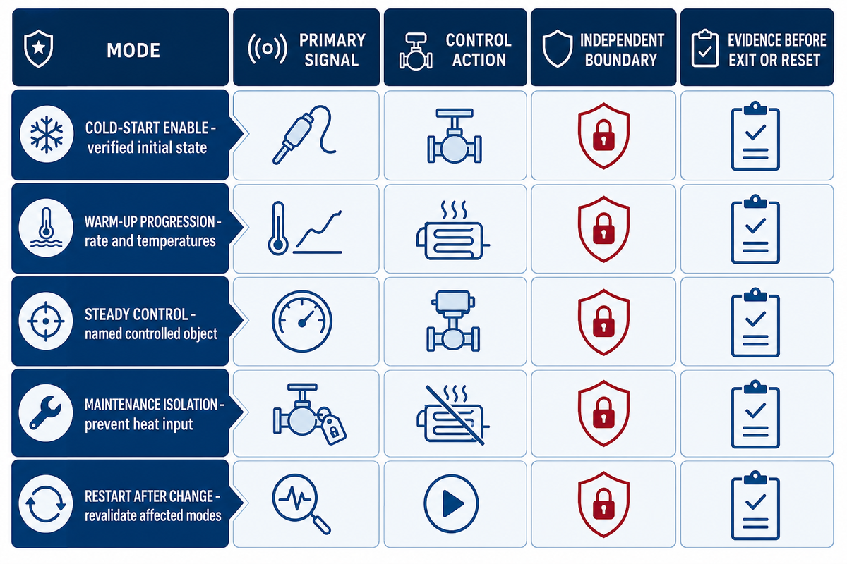
Once each temperature object is named, normal control, alarms, interlocks, and operating transitions have different jobs. Control holds a process variable, an alarm calls for attention, an interlock blocks or changes an action, and a transition moves the system between startup, steady operation, shutdown, and recovery. Each needs its own signal, owner, limit, and evidence.
PID temperature controllers can serve normal regulation, yet a heating control system still needs independent limits and defined transitions. Installing more temperature controllers does not create independent protection when they share the same sensor, logic, power, or unverified process assumption.
Mode–Signal–Action Matrix
Mode–Signal–Action Matrix fields link each operating event to the signal, action, independent boundary, and record that authorizes the next step.
| Mode or event | Primary signal | Control action | Independent boundary | Evidence before exit/reset | Limitation |
|---|---|---|---|---|---|
| Cold-start enable | Verified initial temperatures and material state | Permit controlled heat input | Material, pipe, heater, and area limits | Approved start checklist | Not a universal procedure |
| Warm-up progression | Rate and selected temperature objects | Modulate or stage heat | Maximum rate and secondary temperature | Trend within approved envelope | One location can miss gradients |
| Steady control | Named controlled object | Maintain required window | Independent high/low limit | Stable trend and process condition | Setpoint is not fluid proof |
| High-process alarm | Process variable | Notify and apply approved response | Independent shutdown criterion | Cause and response logged | Alarm is not an interlock |
| High-heater or wall limit | Heater or wall temperature | Reduce or remove input | Qualified construction limit | Limit channel test | Does not prove fluid condition |
| Accessible-surface hazard | Assessed outer-surface exposure | Guard, insulate, restrict, or apply approved control | Current workplace hazard assessment | Documented protective measure | Not an electrical approval |
| Sensor disagreement | Difference between independent readings | Hold transition and diagnose | Approved plausibility band | Calibration and wiring check | Do not average away a fault |
| Utility or circuit loss | Power/steam/circuit state | Enter approved fallback or shutdown | Process time-to-limit | Restoration and condition record | Return of power is not restart proof |
| Maintenance isolation | Energy-isolation state | Prevent heat input | Applicable lockout and thermal-energy controls | Isolation verification | Procedure is site-specific |
| Restart after change | Changed component or assumption | Revalidate affected modes | Design and safety approval | Signed change and restart record | Old baseline may be invalid |
What are the common problems with pipe heaters?
Common system-level problems include a changed heat-loss path, the wrong temperature object being controlled, an open circuit or lost utility, process flow or material changes, disabled alarms, and maintenance that altered insulation or sensing. Physical blanket fit and cable diagnosis need method-specific inspection; this guide focuses on the evidence that tells operators where to look.
An NRC event report linked short cold sections with sensing-element placement and insulation configuration; later actions covered sensors, wiring, insulation, and pyrometer guidance. This event is not a failure rate or a universal procedure. Its value is the coupled mechanism: one cold result can cross controls, electrical, mechanical, and operating records.
“How far above the limit and for how long depends on controller tuning and process gains.”
That quote comes from an override-control furnace example, not a pipe-heating design. Only the principle transfers: primary control and a secondary safety limit can interact and change authority during a disturbance. Define the handoff and reset evidence before commissioning the logic.
Published in 2025, one pipeline-heating patent record models different startup thresholds across ambient conditions while heater power remains constant. Its search record lists a non-FlexBlanket assignee, and a patent is not field validation. Startup logic can still differ from steady-state logic even when power does not change.
Estimate Annual Energy Without Inventing a Savings Claim
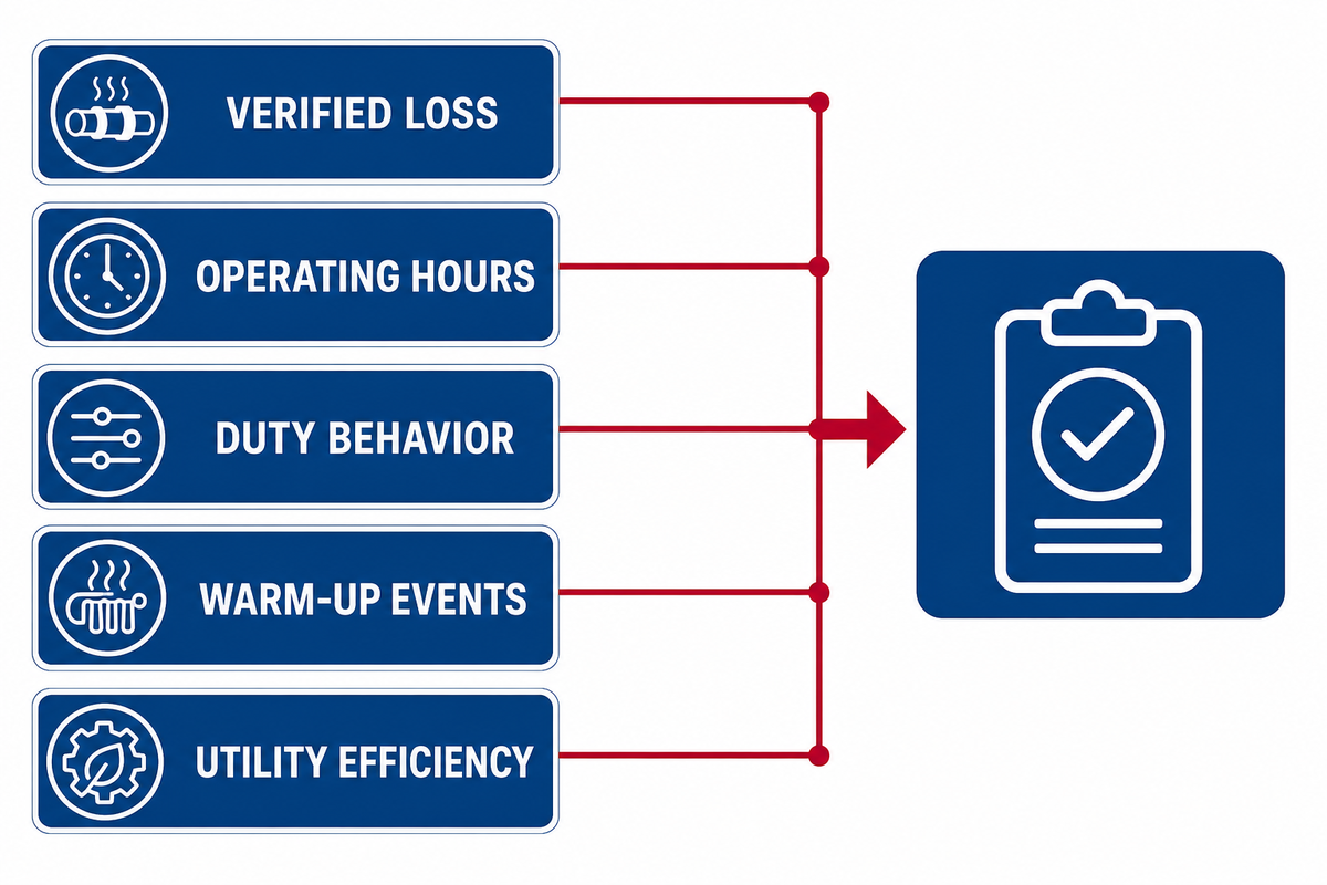
With operating modes and controller behavior defined, annual pipe-heating energy depends on the verified loss for each mode, hours in that mode, warm-up events, and utility efficiency. No product category can supply one defensible savings percentage. Use a worksheet whose inputs operations and finance can replace and audit.
Colorado State University’s energy-balance framework keeps sensible, phase-change, and reaction terms distinct. Annual accounting then adds mode-specific loss, operating time, and utility behavior without converting the example into a performance guarantee.
Are tube heaters expensive to run?
Operating cost can be high or low only relative to the actual heat loss, operating schedule, control behavior, and utility tariff. Continuous operation on a small heater may use more annual energy than brief cycling on a larger unit, while damaged insulation can change either result. Calculate kWh or steam use from dated inputs rather than equipment size alone.
Assume the earlier line has 1.0 kW of verified steady loss, operates 4,000 hours per year, and averages a 0.65 duty factor. Maintenance energy is 1.0 × 4,000 × 0.65 = 2,600 kWh/year. If 100 warm-ups each add 0.333 kWh, annual total becomes 2,633.3 kWh. At an illustrative input of $0.12/kWh, cost is about $316/year.
Replace every number before using the worksheet. The example excludes distribution losses, control-panel loads, heat to hardware, seasonal modes, demand charges, steam generation/distribution efficiency, downtime, and maintenance. It’s a calculation pattern, not an energy guarantee or return-on-investment claim.
Key takeaway
Annual energy becomes auditable when loss, hours, duty behavior, and warm-up events remain separate; a universal savings percentage hides the decision inputs.
Build the Lifecycle Evidence Ledger
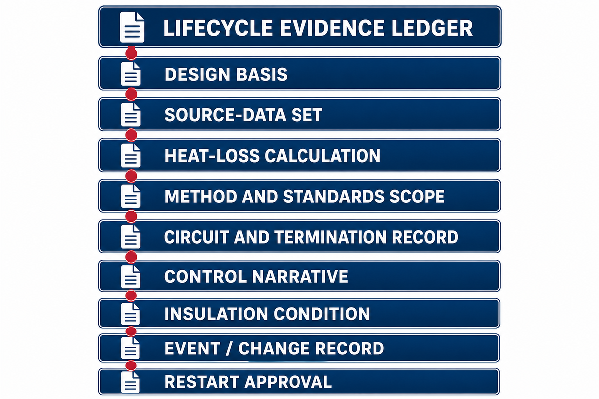
After energy and mode assumptions are recorded, lifecycle evidence keeps the heat balance, controlled object, limits, alarms, insulation state, maintenance changes, work ownership, and restart approval connected. Records matter because replacing a sensor, opening insulation, changing a setpoint, or altering process flow can invalidate evidence created under the previous configuration.
Lifecycle Evidence Ledger
Lifecycle Evidence Ledger fields tell the next reviewer which version of the system was assessed, what changed, who owned the work, and which operating modes were revalidated.
| Record | Minimum fields | Owner | Recheck trigger | Limitation |
|---|---|---|---|---|
| Design basis | duty, material, modes, temperature window, revision | Process | Material or operating-mode change | Does not size hardware alone |
| Source-data set | SDS, drawings, insulation, ambient, flow | Process/Mechanical/EHS | Document revision or field discrepancy | Old documents may not describe the asset |
| Heat-loss calculation | inputs, method, units, assumptions, result | Thermal design | Insulation, ambient, geometry, or mode change | Valid only for its version |
| Method and standards scope | technology family, environment, edition, exclusions | Electrical/EHS | Method, classification, or standard change | One standard does not cover all methods |
| Circuit and termination record | circuit ID, protection, test result, work owner | Electrical | Repair, extension, or fault | Competency evidence is project-specific |
| Control narrative | object, sensor ID, setpoint, alarm, interlock, reset | Controls/Process | Logic, sensor, setpoint, or limit change | Narrative does not prove field operation |
| Insulation condition | date, location, state, repair, reinstatement | Maintenance | Access, water ingress, damage | Visual checks may miss hidden moisture |
| Event/change record | alarm, cause, action, changed assumption, evidence | Operations/Maintenance | Every event or maintenance change | Closeout text cannot replace test data |
| Restart approval | affected modes, test results, approvers, date | Process/EHS/Operations | Before return to service | Approval authority is site-specific |
IEC/IEEE 62395-2:2024 treats design, installation, maintenance, and repair as one lifecycle for electrical resistance trace heating in ordinary industrial and commercial applications. Its title and scope are method-specific; do not apply that evidence to induction, impedance, skin-effect, or direct-pipeline heating.
IEC/IEEE 60079-30-2:2025 is a separate application guide for resistance trace heating in many explosive atmospheres. Its public scope excludes EPL Ga/Da and excludes induction, skin-effect, and direct-pipeline heating. OSHA 1910.307 also requires areas to be considered individually. Neither source classifies a reader’s site or proves a FlexBlanket approval.
Use the pipe heating design record check to organize the project handoff. When a supplier must confirm construction, heat input, controls, or application evidence, review FlexBlanket pipe process heating solutions and the available removable pipe heating blankets. That handoff is for project-specific review, not a substitute for qualified engineering or site safety ownership.
FAQ: Pipe Process Heating
Is pipe process heating the same as a heat pipe used for cooling?
Pipe process heating adds controlled heat to industrial process piping; a heat pipe is usually a passive two-phase heat-transfer device used for cooling or thermal management.
The phrases describe different systems. This guide addresses thermal energy supplied to an industrial pipe and process fluid. A cooling heat pipe transfers heat through evaporation and condensation of a working fluid inside a sealed device. Searches for a heat pipe working principle or heat pipe cooling system usually concern that passive device, not controlled process-pipe heating. Confirm which meaning a drawing, specification, or supplier page uses.
What is transfer of heat through a metal pipe called?
Heat moving through the metal pipe wall is conduction, but a complete pipe-heating system also involves convection between the wall and fluid plus radiation at exposed surfaces.
Conduction moves thermal energy through the pipe wall. Heat then crosses interfaces between the heater, pipe, insulation, surrounding air, and process fluid. Fluid-side convection links wall and material, while outer-surface convection and radiation release heat to the surroundings. Contact resistance and changing insulation condition also matter. One wall-conduction equation is therefore not a complete pipe heat-loss model.
What are the four types of heating systems?
Industrial process heating has no universal four-type list; Department of Energy guidance uses three broad categories, and pipe methods require a second classification for the application.
Department of Energy guidance uses three broad categories: fuel-fired, steam-based, and electric. Pipe applications can then be subdivided into resistance tracing, surface heating, impedance, induction, direct-pipeline, or other methods. Another valid taxonomy may group systems by direct or indirect transfer. Use the classification that matches the engineering decision instead of forcing every technology into four boxes.
Does insulation always reduce required heating power?
Intact, correctly specified insulation usually reduces heat loss, but required heating power still depends on its current moisture, compression, joint, and weather-barrier condition in service.
Thickness, thermal conductivity, compression, moisture, open joints, supports, and weather barriers affect performance. Calculations based on dry new insulation may no longer represent a wet or disturbed system. Record condition, location, and inspection date; then rerun each affected loss case after repair or access. Compare the new result with heater capacity and control limits before restart. Insulation also changes the employee-accessible surface, so energy and contact exposure require separate checks. Hidden moisture and local gaps can remain even when most of the jacket looks intact.
Can one setpoint govern startup and steady operation?
One setpoint cannot govern startup and steady operation because each mode may require a different rate, hold point, alarm, interlock, and distinct restart approval evidence.
Startup begins with a different thermal state and may need a controlled rate, independent limits, sensor agreement, and evidence before flow begins. Steady operation focuses on maintaining the named control object. Shutdown and recovery introduce their own material and time constraints. Define each mode in the control narrative rather than treating the normal setpoint as the whole procedure.
When should a hazardous-area specialist review pipe heating?
Hazardous-area review belongs before equipment selection whenever flammable materials, gases, vapors, dusts, or fibers can affect classification, method scope, circuit protection, or assigned approval responsibility.
Site ownership must establish the applicable classification and protection level using current jurisdictional requirements. Resistance trace heating in many explosive atmospheres has a separate IEC/IEEE 60079-30-2:2025 application branch, but that page excludes EPL Ga/Da and several heating methods. Generic IP ratings, ordinary-location standards, product photos, or sales descriptions do not establish suitability. Obtain project-specific classification, method scope, equipment evidence, circuit-protection requirements, installation rules, inspection records, and approval responsibility. Reopen the review after material, ventilation, zoning, heater method, wiring, or maintenance changes. This article cannot determine whether any particular location or product is acceptable. Document the classification basis and designated approver in the lifecycle ledger so a later repair cannot silently inherit an obsolete decision.
Evidence and Scope Note
This article separates public authority evidence from illustrative calculations and supplier claims. It doesn’t publish FlexBlanket project data, certifications, patents, customer endorsements, or universal performance values. Project numbers belong in a dated design record reviewed by the responsible process, electrical, mechanical, controls, maintenance, and safety roles.
Related Articles
- silicone and flexible heaters product-family context for industrial surface heating.
- custom heating blankets and OEM options commercial custom-build scope.
- silicone rubber heater selection guide surface-heater selection and use.
- silicone drum heater guide container-heating selection and operation.
References & Sources
- Process Heat Basics U.S. Department of Energy
- What Are the Different Kinds of Process Heating Systems? U.S. Department of Energy
- Insulated Pipe Reduction Calculator Documentation Oak Ridge National Laboratory
- Energy Balances Colorado State University
- On-Site Temperature Feedback Control Study Micromachines / PubMed Central
- ASTM C1055-20 ASTM International
- Ensuring the Right Controller Is in Charge Control Global
- Licensee Event Report 99-001-00 U.S. Nuclear Regulatory Commission
- CN120317003A Pipeline-Heating Patent Record Google Patents; non-FlexBlanket assignee shown in the record
- IEC/IEEE 62395-2:2024 International Electrotechnical Commission
- IEC/IEEE 62395-1:2024 International Electrotechnical Commission
- IEC/IEEE 60079-30-2:2025 International Electrotechnical Commission
- Safety Data Sheets, Appendix D Occupational Safety and Health Administration
- Hazardous (Classified) Locations, 1910.307 Occupational Safety and Health Administration