Get in touch with FlexBlanket Company

Wind Turbine Blade Curing Blankets for Rotor Blade Repair | Flex
Wind turbine blade curing blankets from Flex deliver controlled electric heat to epoxy, prepreg and adhesive repair zones across curved composite surfaces. Each blanket is configured around the heated area, available power, zone layout and controller interface—not just nominal width and length.
- 120 VAC or 230 VAC
- 800 W/m² +15%
- 100°C maximum
- 250 / 400 / 650 / 900 mm heating widths
- Lengths up to 15 m
SYS_STATUS: READY
ZONE_FIT: VERIFIED
Check Thermal Fit and Load
Send the repair-zone sketch, approved cure profile, site voltage and control interface. We use those inputs to define the blanket and electrical package for quotation.
Voltage choices
120 VAC or 230 VAC
Nominal power density
800 W/m² +15%
Temperature ceiling
100°C / 212°F
Standard widths
Four heated-area bands
Length range
Up to 15 m
Control
Programmable controller
COMPOSITE CURING BLANKET
ENGINEERING SPECIFICATION
Wind Turbine Blade Repair Heating Capabilities
Flex supplies a lightweight, conformal heat blanket for localized composite curing, with a graphene heating layer, programmable temperature controller and 450/750 V power cord. The blanket also includes insulation and a marked working zone for epoxy resin, adhesive and prepreg cure work where the approved material process stays within the specified temperature and electrical limits. Wind-blade repair patents place the heater inside a controlled stack of contact, sensing and compaction, so our quotation separates the blanket from the rest of the repair system.
CAPABILITY 01
Heat where the repair sits
A marked heating area separates the active zone from the overall blanket edge. That distinction matters when a repair approaches a leading edge, trailing edge or taper.
CAPABILITY 02
Controls matched to the job
We quote custom dimensions, voltages, power ratings, heating zones and control options around the submitted requirement. The final sensor, connector and circuit plan still has to agree with the buyer’s repair equipment.
CAPABILITY 03
Field handling details
A 5 mm insulation build includes hook-and-loop attachment and visible heating-zone marks for placement and repositioning. Mass is specified as 1.6 +0.3 kg/m² in the supplied product data.
CAPABILITY 04
Electrical facts, not a field approval
The product data lists AC 3000 V at 50 Hz for 1 minute, a 2 m cable and a 16 A three-pin industrial plug. Those entries do not by themselves establish approval for a wet, conductive, outdoor or elevated job location.
CAPABILITY 05
Material scope
Flex manufacturing review treats this product as a wind-energy composite curing heating blanket, not an aerospace heater. Do not infer radiation resistant, silicone or silicone rubber construction unless the quotation states that material.
CAPABILITY 06
Placement and acceptance
For a horizontal shop repair or vertical up-tower placement, define the contour, composite material, attachment and ambient exposure. The buyer may be a wind turbine blade repair service team or a wind turbine blade maintenance group; Flex supplies the heating product rather than the repair labor. The curing process, temperature control, heat distribution target and durability requirement must be tied to a test method; a request for uniform heat alone is not an acceptance criterion.
We stop a blanket specification when heated area, local voltage, sensor plan and cure profile do not agree. A width-and-length match is not enough.— Flex Application Engineering Team
APPLICATION VISUALS
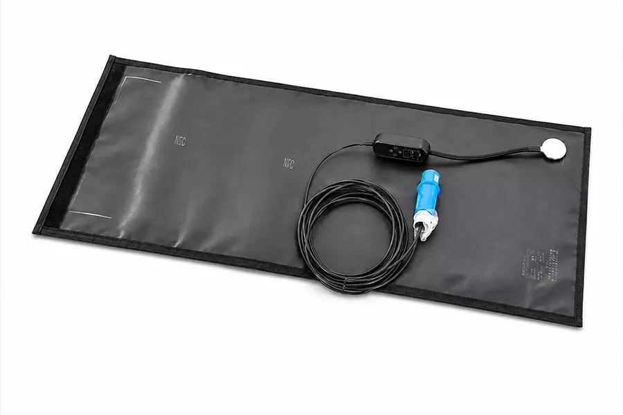
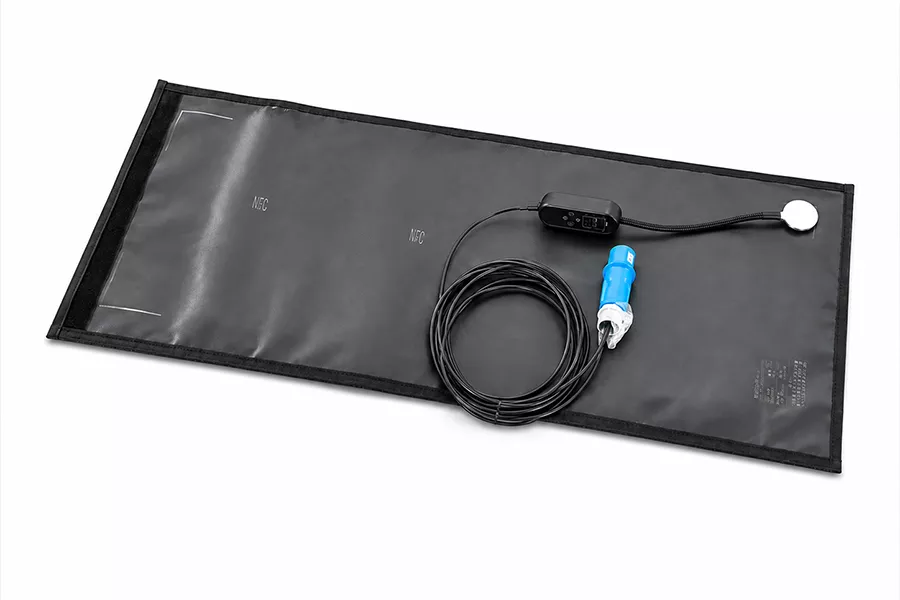
Complete blanket assembly. This image verifies the physical product layout, not a measured cure result.
Standard Blanket Sizes and Custom Heating Zones
Heating width is the active band; blanket width includes the surrounding construction and attachment area. Put both values on the RFQ so the heated footprint is not mistaken for the physical edge-to-edge size.
Heating width
Overall blanket width
Listed length
RFQ check
250 mm
350 mm
Up to 15 m
Confirm edge clearance and heated-zone placement.
400 mm
500 mm
Up to 15 m
Check local heat sinks and the planned sensor line.
650 mm
750 mm
Up to 15 m
Review zone count and circuit split before release.
900 mm
1000 mm
Up to 15 m
Do not assume one connector supports the full load.
Eight-Input Thermal Fit Review
01
Curvature Radius
Click to View >Curvature radius at the repair and at any blade edge.
02
Material Comp
Click to View >Laminate and core material beneath the repair.
03
Local Thickness
Click to View >Local thickness and thickness transitions.
04
Heated Area
Click to View >Required heated area, separate from overall blanket size.
05
Attachment Method
Click to View >Contact and attachment method across the complete zone.
06
Heat Sinks
Click to View >Metal inserts, tooling or other local heat sinks.
07
Insulation Stack
Click to View >Insulation stack above the heater and vacuum-bag arrangement.
08
Environment
Click to View >Ambient temperature, wind exposure and work-location limits.
Notice: A blanket can match overall width and length yet bridge at a tight radius. A published composite-repair practitioner warns that the same blanket can bridge or wrinkle even when it appears to conform, while a wind-blade patent describes the fold problem as a route to local overheating.
Build a Thermal-Fit Brief
TGT_ZONE: ALIGNED
BND_CHK: VISIBLE
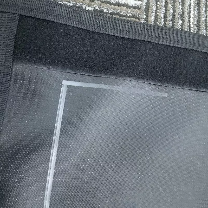
Marked heating zone on a Flex wind blade curing blanket
The visible boundary helps align the active zone with the repair sketch.
MCH_FIT: PENDING
CNT_CHK: REQ_GEOMETRY
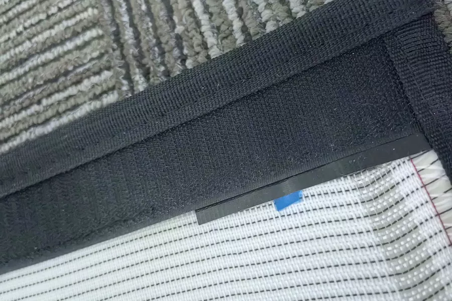
Hook-and-loop attachment detail on a Flex curing blanket
Attachment detail. Contact still has to be checked on the real blade geometry.
Blade Curvature, Contact and Zone Configuration
Often, the hardest heating problem is hidden under a size match. Tight radii, compound corners, thickness changes and local heat sinks can move the thermal load away from the condition assumed at the controller.
Failure Route
Bridging leaves an air gap and changes heat transfer.
Specification Response
Supply radius, section drawing and attachment plan.
Failure Route
Folds can concentrate heat or lift another area.
Specification Response
Review shaped geometry, separate zones or another heat route.
Failure Route
Thick and thin areas respond at different rates.
Specification Response
Map thickness bands and sensor positions.
Failure Route
A local heat sink pulls energy from the repair zone.
Specification Response
Identify inserts, tooling and contact materials.
Failure Route
One zone can hide a large thermal difference.
Specification Response
Review overlapping blankets or separately controlled zones.
Failure Route
Heat loss changes the power needed at the laminate.
Specification Response
Define ambient range and insulation before sizing.
Temperature, Power and Electrical Specifications
Product data provides a firm electrical and dimensional baseline. Use it to screen a project, then confirm current, zone count, connector, cable and protection for the actual heated area; equipment used in a conductive or wet location also needs approval for that location.1
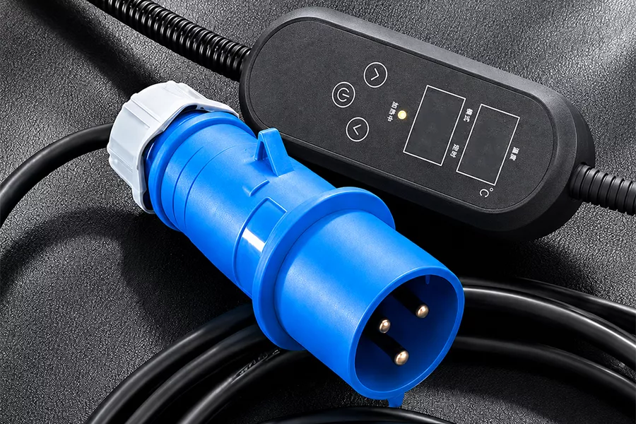
16 amp three-pin industrial plug supplied on a Flex curing blanket
The connection shown in the product data. Final current and connector scope depend on the blanket design.
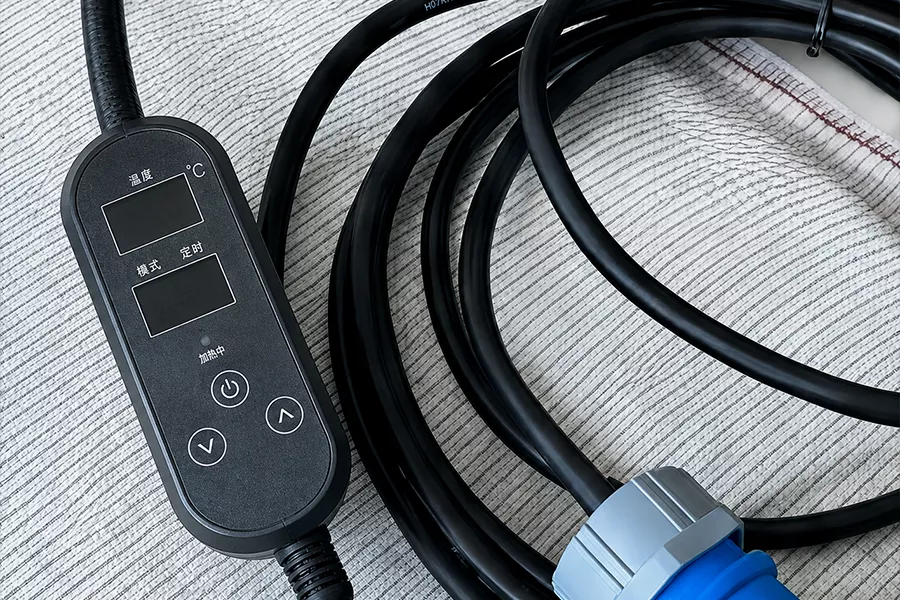
Flex temperature controller and high-voltage-resistant power cord
Controller and cable detail for interface review.
Project Scoping Specifications
Specification
Flex product data
Release note
Operating voltage
120 VAC or 230 VAC
Confirm site supply and circuit design.
Nominal power density
800 W/m² +15%
Literal PDF notation; not a uniformity claim.
Maximum temperature
100°C (212°F)
Compare with the approved resin profile.
Dielectric-strength entry
AC 3000 V, 50 Hz, 1 min
Not a wet-location or field-use approval.
Mass
1.6 +0.3 kg/m² with 5 mm insulation
Check handling and overhead support.
Power cable
2 m (6.5 ft); 450/750 V cord
Confirm route and connector location.
Plug shown
16 A, 3-pin industrial plug
Not an all-size current rating.
Heating widths
250 / 400 / 650 / 900 mm
Keep separate from blanket width.
Blanket widths
350 / 500 / 750 / 1000 mm
Physical edge-to-edge dimension.
Listed length
Up to 15 m
Long lengths can require zone and circuit splitting.
Custom choices
Dimensions, voltage, power, zones and controls
Each choice is confirmed in the quote.
Electrical load is an area calculation
Theoretical power equals heated width × heated length × 800 W/m². A 900 mm × 15 m heated area is 13.5 m², which gives 10,800 W nominal; dividing by voltage gives about 90 A at 120 V or 46.96 A at 230 V.
At the PDF’s +15% scenario, the same area is 12,420 W. These values screen RFQ risk only; they are not a wiring design or a statement that this maximum size runs on one connector.
QUOTE // MATRIX
Quote Inputs and Project Handoff
Price reflects heated area, blanket geometry, power, number of zones, controller scope, connector package, sensing, testing and quantity. Lead time is set after the same design release and stated in the written quotation. This page does not publish borrowed price, MOQ or delivery figures.
Cost searches need a common boundary
Two quotations with the same blanket dimensions can contain different control, connector, test and document scopes. An inquiry for composite curing blanket cost or epoxy curing blanket cost still needs the heated area, electrical load, sensing and acceptance scope. A hot bonder wind turbine blade repair cost request includes system functions that a standalone blanket quote may not include.
Quote-Normalization Grid
Cure-Profile and Controller Configuration
The blanket specification does not create the resin recipe. Send the cure profile approved by the resin, adhesive or repair-process owner, including setpoint, ramp rate, hold time, permitted spread, cool-down and the point where temperature is measured.
Cure-Profile Input Brief
01Material and batch identification
02Setpoint and ramp rate
03Hold duration and allowed temperature band
04Cool-down or release condition
05Measurement inputs
06Thermocouple type and quantity
07Sensor location at heater, laminate or bond line
08Connector design and calibration evidence
09Required data record and sampling interval
The controller can report its sensor circuit correctly while the laminate sees a different thermal condition. ASTM E2820-13(2024) is not a heating-blanket standard; its narrow value here is measurement discipline because a thermocouple connector exposed to a temperature gradient can add error, and the error depends on connector design.
Do not reuse a recipe from another resin system. Flex configures the heater and controller around the approved input; the repair authority owns the cure acceptance criteria.
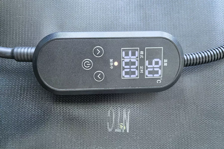
Programmable temperature controller on a Flex composite curing blanket. The controller shows set and measured temperature fields; sensor placement and acceptance still belong in the RFQ.
Quality Checks and Acceptance Evidence
Acceptance starts before fabrication: define which dimensions, electrical checks, interface checks and temperature observations will release the blanket. The supplied product data supports a dielectric-strength entry and component identification, but it does not establish a calibration program or a field-performance result.
A failure route opens when acceptance criteria are added after fabrication because the build and the test can then describe different configurations. Flex engineers the quotation around the frozen input and six release steps. The 800 W/m² +15% entry remains a product-data fact, not a temperature-map acceptance limit.
Configuration Requirement
Record heated area, overall geometry, voltage, zones, controller and connector.
Configuration Requirement
Confirm theoretical load, circuit split, cable, plug and protection.
Configuration Requirement
Name thermocouple type, location, connector and record requirement.
Configuration Requirement
Check dimensions, zone marks, attachment, cable, connector and controller against the released specification.
Configuration Requirement
Apply electrical and functional tests under the written method.
Configuration Requirement
Keep the acceptance record tied to the configuration quoted.
Product Construction and Control Details
Nine supplied real product photographs give procurement and engineering teams a clear view of the attachment, marked active zone, controller, cable, plug and heating-layer construction before an RFQ is released. A wind-blade repair patent shows why the heater and thermocouple belong inside a larger controlled process, so use these views to identify interface questions before quotation.5
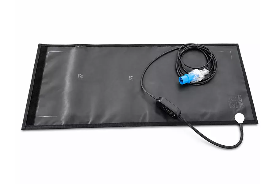
Flex wind turbine blade curing blanket shown with controller and cable
Complete assembly with the heating zone marked on the blanket face.
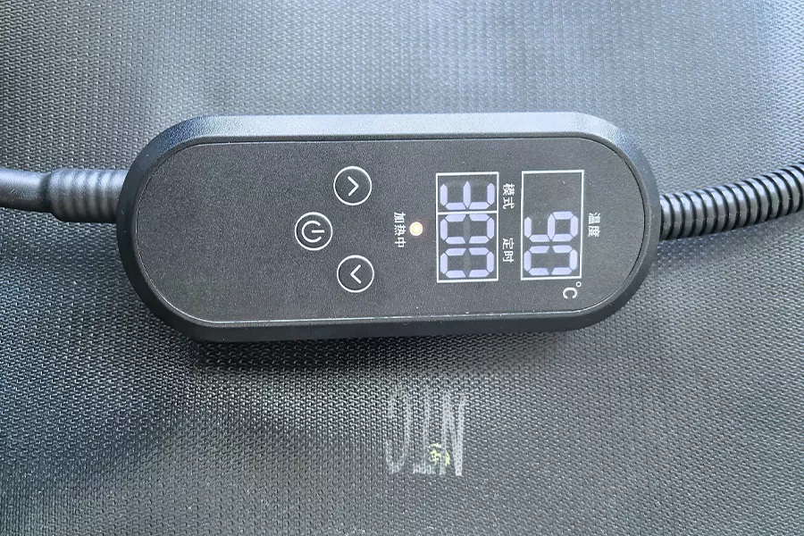
Hook-and-loop edge and marked active heating zone on a Flex blanket
Attachment and zone-boundary detail for placement review.
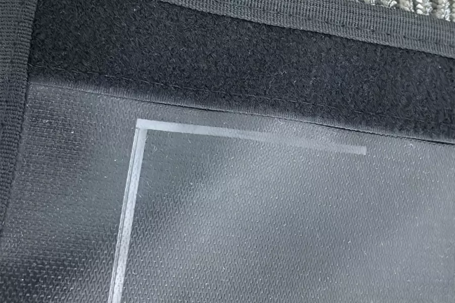
Digital temperature controller display on a Flex curing blanket
Controller interface. Accuracy and sensor scope are confirmed per project.
Curing Blanket and Hot Bonder System Boundaries
A heating blanket supplies heat. A complete composite-repair setup may also need vacuum, compaction, thermocouples, closed-loop control, multi-zone power and a retained cure record.
Heating blanket
Decision it owns
Heated footprint, watt density and physical contact
Release evidence
Released dimensions, zones and electrical design
Temperature controller
Decision it owns
Setpoint, ramp, hold and output switching
Release evidence
Controller specification and channel mapping
Thermocouple circuit
Decision it owns
Where temperature is measured
Release evidence
Type, location, connector and calibration scope
Hot bonder
Decision it owns
Integrated heat/vacuum sequence and data record where fitted
Release evidence
Interface list and approved program
Vacuum-bagging system
Decision it owns
Compaction, seal and pressure boundary
Release evidence
Repair procedure and leak acceptance
Repair authority
Decision it owns
Material recipe and structural acceptance
Release evidence
Approved repair instruction
Do not call a blanket plug-and-play with an existing hot bonder until connector, thermocouple, zone and load interfaces have been reviewed. Patent material shows possible system arrangements; it does not certify a Flex interface.
Application Limits and Alternative Heating Routes
Condition // 01
Approved cure temperature above 100°C
The product-data ceiling is lower.
Review another heater construction or process.
Condition // 02
Tight compound radius
Bridging and wrinkles can change contact.
Use shaped zones, another heater form or a validated setup.
Condition // 03
Wet or conductive job location
Dielectric test data is not location approval.
Use equipment approved for that location and confirm safe connections.1
Condition // 04
Need for vacuum and retained cure data
A standalone blanket does not provide the complete process.
Specify the hot bonder, vacuum and data-record boundary.
Condition // 05
Large theoretical current
One 16 A connection cannot be assumed for every area.
Split zones/circuits and confirm the electrical design.
Where to look instead
The wrong choice is forcing one blanket format onto a repair whose temperature, geometry or location falls outside the released scope. A blanket is not a substitute for vacuum, structural approval or a cure record when the repair procedure requires them. The trade-off is between a conformal local heat source and the extra process equipment needed to control the whole repair.
Wind Turbine Blade Curing Engineering Tools
Thermal Fit & Load Check
Verify curvature radius, thickness transitions, and heat sink impacts for your specific blade repair geometry.
Open Fit & Load CheckElectrical Load & Circuit Check
Map voltage, nominal watts, current requirements, and zone distributions against your site power supply.
Open Circuit CheckCure Profile RFQ Builder
Define target temperature ceilings, ramp rates, and control interfaces to generate accurate blanket specifications.
Open RFQ BuilderQuote Normalization Builder
Compare supplier proposals based on equal boundary conditions including sensing, testing, and documentation scopes.
Open Normalization BuilderWind Turbine Blade Curing Blanket FAQs
Q.
What is the difference between heating width and blanket width?
What is the difference between heating width and blanket width?
Heating width is the active thermal band. Blanket width includes the surrounding construction and attachment area, so a 250 mm heated zone is listed with a 350 mm overall blanket width.
Q.
Which standard widths are listed?
Which standard widths are listed?
The product data lists heating widths of 250, 400, 650 and 900 mm with overall widths of 350, 500, 750 and 1000 mm. Each is listed up to 15 m long, subject to load, zone and circuit review.
Q.
Can Flex configure both 120 VAC and 230 VAC blankets?
Can Flex configure both 120 VAC and 230 VAC blankets?
Yes. The product data lists 120 VAC and 230 VAC; the RFQ still has to state local supply, heated area, theoretical load, circuit split, cable and connector.
Q.
Does the 16 A plug support every blanket size?
Does the 16 A plug support every blanket size?
No such assumption is safe. Current follows heated area, watt density and voltage, so larger or longer blankets can require more than one zone, circuit or connection.
Q.
How do I submit a ramp-and-soak cure profile?
How do I submit a ramp-and-soak cure profile?
Attach the approved material or repair-process profile with setpoint, ramp, hold, cool-down, allowed temperature spread and sensor position. Use the cure-profile RFQ builder to format the inputs.
Q.
When should a repair use multiple heating zones?
When should a repair use multiple heating zones?
Review multiple zones when the heated area is long, thickness changes, contact conditions differ or separate areas need independent control. The final decision follows the thermal and electrical review.
Q.
Can the blanket connect to an existing hot bonder?
Can the blanket connect to an existing hot bonder?
Only after interface review. Provide the hot-bonder model, output rating, connector, thermocouple type, zone count and required control/data functions.
Q.
Is the 100°C maximum suitable for every epoxy or prepreg?
Is the 100°C maximum suitable for every epoxy or prepreg?
No. Compare the approved cure profile with the 100°C product-data ceiling; a material that requires a higher temperature needs another heater or process route.
Q.
How should temperature uniformity be specified?
How should temperature uniformity be specified?
Name the measurement surface, sensor locations, allowed spread, ambient condition, insulation stack and hold period. Thermocouple-connector design and temperature gradient can also affect the measurement circuit.
Q.
What information is required for a custom quote?
What information is required for a custom quote?
Send heated and overall dimensions, curvature, laminate/core, thickness, voltage, target profile, zones, sensor/controller interface, quantity, job location and acceptance scope.