Get in touch with FlexBlanket Company

Updated August 2026
Silicone rubber heaters are flexible resistance elements that place electrical heat close to a surface, but the heater alone does not determine the installed temperature. The heat sink, contact, circuit pattern, insulation, sensor and controller form one system. This guide helps an industrial buyer define that system before a custom configuration is released.
Direct answer
A silicone rubber heater is a flexible resistance heating element laminated in silicone and applied to a defined heat sink. Selection starts with the heated object and measurement objective—not a catalog watt density—because contact, geometry, ambient losses and control determine the operating result.
What to remember
- A product-family rating is not an installed-surface guarantee.
- Wire-wound and etched-foil are circuit architectures, not a universal good-versus-bad choice.
- A sensor must represent the temperature the loop is meant to control.
- Electrical, ingress, touch-safety and hazardous-location evidence have different scopes.
Quick decision inputs
| Input | Question it answers |
|---|---|
| Heat sink | Where can electrical heat flow? |
| Contact and geometry | Where can a gap or local mass alter the temperature field? |
| Measurement plane | Which temperature should the controller represent? |
| Protection evidence | Which instruction, test or approval governs the installed assembly? |
How Silicone Rubber Heaters Turn Electricity Into Surface Heat
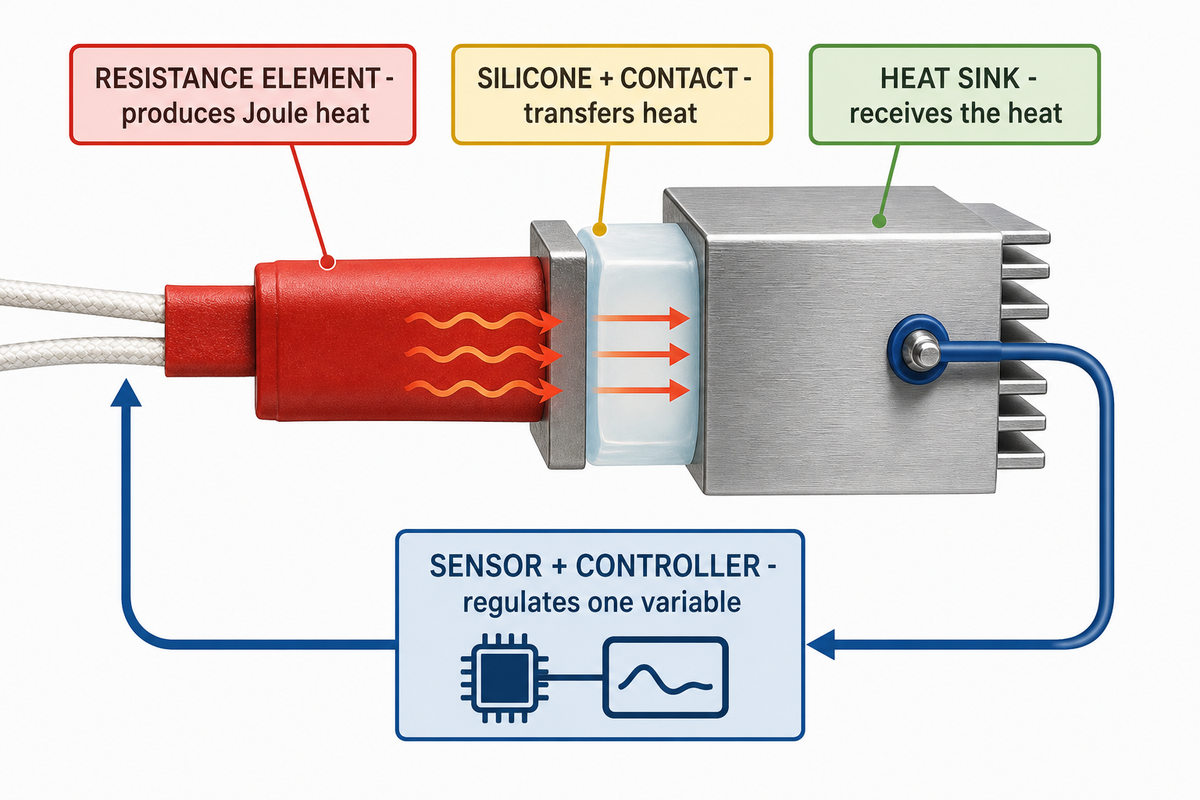
A silicone rubber heater converts electrical power into heat inside a flexible laminate, then conducts that heat into the contacted substrate. The substrate acts as the heat sink. A thermostat or temperature sensor and its controller regulate the circuit, while insulation and ambient conditions determine how much heat escapes.
How do silicone heaters work?
Current passes through a resistance element, producing Joule heat. That heat crosses the silicone insulation and contact interface before entering the heated object. If contact changes, the same electrical input can produce a different heater temperature because the heat path—not just the nominal wattage—has changed.
NASA’s thermal-control overview describes electrical resistance heaters controlled by thermostats or temperature sensors, including closed-loop feedback in active systems. The spacecraft examples do not transfer product ratings to industrial silicone heaters; they establish the narrower architecture: heater, load, feedback and controller must be reviewed together.
IEC/IEEE 62395-1:2024 places heater pads and panels inside its electrical resistance trace-heating scope when they are assembled and terminated to the manufacturer’s instructions. That wording does not make the standard a silicone-specific design code, and it expressly excludes potentially explosive atmospheres.
Wire-Wound and Etched-Foil Are Different Circuit Architectures
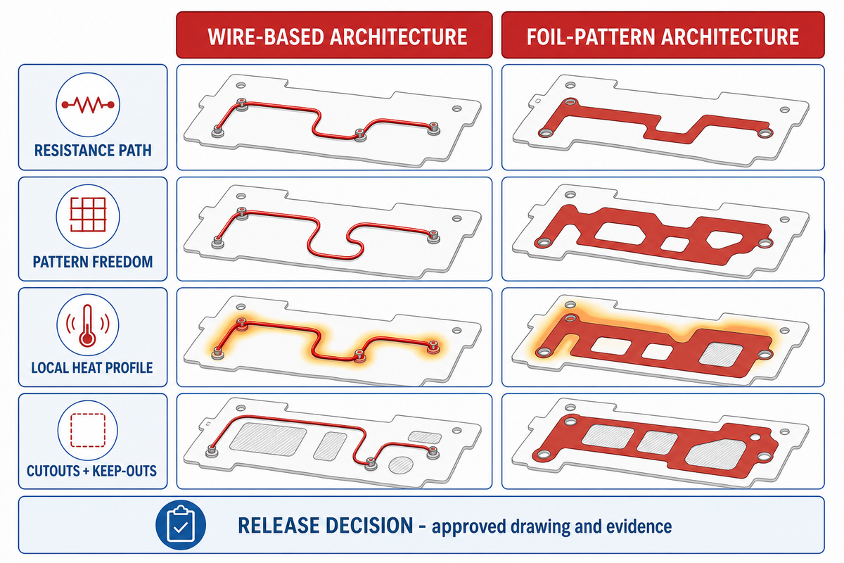
Wire-wound and etched-foil designs create resistance paths in different ways, yet the available independent evidence does not justify a universal winner for performance, cost or service life. The useful comparison is architectural: how each route handles path length, patterning, geometry, terminations and the supplier’s manufacturing constraints.
| Design question | Wire-based architecture | Foil-pattern architecture | Evidence boundary |
|---|---|---|---|
| Resistance path | A conductive wire forms the heat path. | A patterned metal foil forms the heat path. | Architecture description only. |
| Pattern freedom | Depends on wire routing and spacing. | Depends on etched path geometry. | No general precision ranking. |
| Local heat profile | Requires a supplier-designed route. | Requires a supplier-designed pattern. | No catalog assumption. |
| Cutouts and keep-outs | Wire must route around them. | Foil path must route around them. | Drawing review required. |
| Lead connection | Construction-specific termination. | Construction-specific termination. | Supplier evidence required. |
| Thermal uniformity | Depends on path, spacing and stack. | Depends on path, spacing and stack. | Not guaranteed by label. |
| Mechanical flexibility | Must be verified for the complete laminate. | Must be verified for the complete laminate. | No universal winner. |
| Production economics | Depends on design and supplier process. | Depends on design and supplier process. | Request quote-specific basis. |
| Release decision | Approved drawing and evidence. | Approved drawing and evidence. | Do not rank from generic copy. |
“Certain spacing needs to be retained between serpentine heat sources for deformation.”
The study examines a different stretchable construction, so its values do not transfer. Its mechanism is still useful: source spacing and material conductivity can affect the temperature field. Shanghai Normal University patent CN113630915A describes wire-based and foil-pattern microheaters; its ownership and micro-scale process do not establish FlexBlanket construction.
Start With the Heat Sink and Thermal Duty
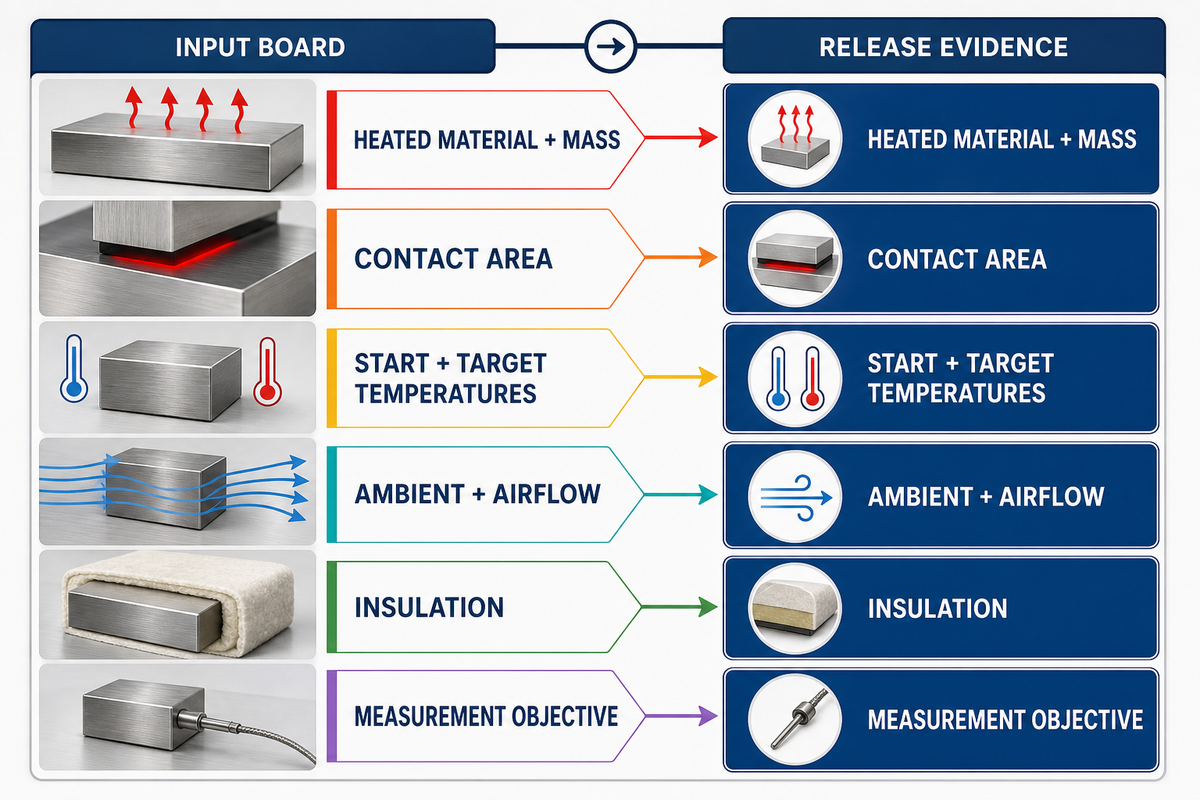
Watt density is a calculation basis, not a complete heater selection. A defensible thermal duty fixes the heated material and mass, contact area, starting and target temperatures, minimum ambient, airflow, insulation, allowed warm-up time and control objective before power is reviewed.
NIST defines heat flux as the rate of heat energy transferred per unit surface area, commonly expressed in kW/m². Dividing nominal watts by nominal heater area can therefore describe a stated electrical loading. It cannot predict the final temperature unless the heat-storage and heat-loss boundaries are also defined.
Worked relationship—not a sizing result
Electrical checks can use P = V × I, R = V² ÷ P and nominal area loading q″ = P ÷ A. The result stays provisional until the heat sink, contact, insulation, ambient and feedback objective are bound. No sample wattage is supplied because a context-free example would look transferable when it is not.
Normalize Units Before Comparing a Design
The following record demonstrates unit discipline with fictional inputs. A 200 mm × 100 mm outline has 20,000 mm², or 200 cm², of nominal area. At an illustrative 100 W and 24 V, the arithmetic gives 4.17 A, 5.76 Ω and 0.50 W/cm². Replace every value with the approved project basis.
| Field | Illustrative entry | Calculation or check | Do not infer |
|---|---|---|---|
| Outline | 200 mm × 100 mm | Confirm heated versus unheated zones. | Final heater shape. |
| Nominal area | 20,000 mm² = 200 cm² | Check unit conversion. | Effective contact area. |
| Power | 100 W | Illustrative input. | Recommended power. |
| Supply | 24 V | Match the site source. | Available current. |
| Nominal current | 4.17 A | 100 W ÷ 24 V. | Switch rating. |
| Nominal resistance | 5.76 Ω | 24 V squared ÷ 100 W. | Measured cold resistance. |
| Nominal area loading | 0.50 W/cm² | 100 W ÷ 200 cm². | Application limit. |
| Temperature objective | 20 °C to 80 °C | Define measurement plane. | Heater limit. |
| Allowed time | 10 min | State load and ambient. | Guaranteed warm-up. |
| Insulation trial input | 5 mm | Bind material and coverage. | Approved stack. |
One peer-reviewed microheater model used a 1 cm × 1 cm sample, a 150 μm substrate, 1.5 V input and a 20 °C initial condition. Those numbers are useful precisely because they expose the boundary conditions; they are not industrial silicone settings. Change the geometry or environment and the result changes.
| Input | Why the thermal result depends on it | Release evidence |
|---|---|---|
| Heated material and mass | Sets heat storage and spreading. | Drawing or bill of material. |
| Contact area | Defines the conductive path. | Contact-zone drawing. |
| Start and target temperatures | Define stored-energy change. | Operating requirement. |
| Ambient and airflow | Change convective loss. | Worst-case envelope. |
| Insulation | Changes outward heat loss. | Installed stack. |
| Measurement objective | Defines what the loop regulates. | Sensor and acceptance plan. |
Fit Geometry, Mounting and Insulation to the Heat Path
Geometry is part of the thermal circuit. Holes, cutouts, thick bosses, clamped edges and unsupported spans alter the route from resistance element to heat sink. Attachment determines contact; outward insulation determines loss. These decisions must be made together, not after a nominal heater outline is chosen.
The 2022 orthotropic flexible-heater model found that heat-source spacing and directional conductivity in the substrate or encapsulation affect thermal uniformity. A separate study found that wire shape and thermal boundaries changed surface distribution. Neither study uses an industrial silicone laminate, so the article carries the mechanism—not the study’s performance values.
| Observed geometry | Possible heat-path effect | Buyer action | Limitation |
|---|---|---|---|
| Through-hole or cutout | Interrupts element routing and contact. | Mark heated and keep-out zones. | No generic edge clearance. |
| Thick boss or fastener land | Creates a local heat sink. | Identify mass and contact area. | Requires thermal review. |
| Curved surface | Can open gaps when attachment is weak. | Define radius and retention. | Flexibility alone is not contact proof. |
| Insulated top face | Reduces outward loss and can raise heater temperature. | Submit the complete stack. | Do not add insulation after release. |
| Serviceable assembly | Permanent bonding can block access. | Choose removable or permanent intent early. | Method depends on actual equipment. |
Place the Sensor for the Temperature You Need to Control
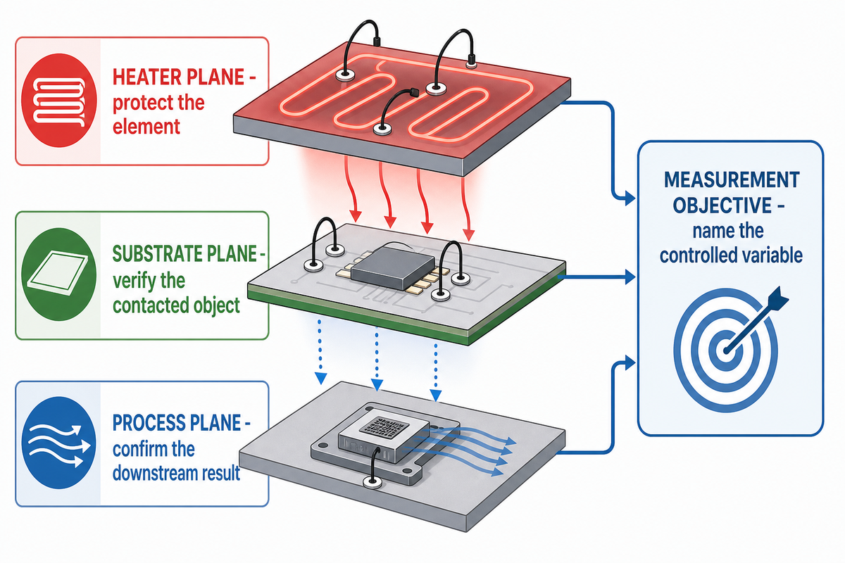
Sensor placement starts with a measurement objective. Heater-surface temperature protects the element, substrate temperature represents the contacted object, and process temperature represents the downstream outcome. One sensor can be useful without representing all three. The control drawing should name the plane, point and acceptance tolerance.
Where should the sensor be placed on a silicone heater?
Place the sensor where it best represents the variable the control loop must regulate, then verify that point against other critical locations during commissioning. A sensor on the heater may protect the laminate, while a sensor on the substrate or in the process may answer a different question.
Use the 3-Plane Temperature Evidence Test
A Scientific Reports study used a dense printed array to map spatial temperature. Its 100 sensor pixels/cm² and reported 1.22 °C prediction accuracy belong to that study’s materials, micro-heater and model; they are not specifications for an industrial silicone heater. The transferable lesson is narrower: a temperature field needs spatial evidence.
| Plane | Question | Evidence to record | Failure if confused |
|---|---|---|---|
| Heater plane | Is the element inside its released limit? | Sensor identity, position and limit action. | Process may remain cold while heater is protected. |
| Substrate plane | Is the contacted object at target? | Measurement point and local map. | A cold or hot zone can remain hidden. |
| Process plane | Did the process outcome reach its target? | Independent process measurement. | Thermal lag can be mistaken for heater error. |
Install Without Creating a Hot Spot
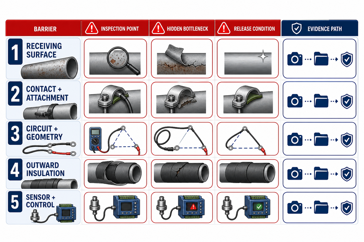
A hot spot is a local heat-transfer failure until evidence shows otherwise. Surface damage, an air gap, a mismatched circuit path, changed insulation or a misplaced sensor can raise local heater temperature. Lead exits add another risk: strain, sharp bends and nearby edges can damage insulation without changing the setpoint.
Can a silicone heating pad be installed with adhesive or clamps?
Adhesive and clamping are possible attachment concepts, but the released method must match the substrate, temperature, contact, service access and heater construction. The correct method is the one documented for the quoted assembly. A generic attachment label does not prove full contact or safe lead routing.
Do
- Inspect the heater and receiving surface before installation.
- Mark contact zones, cutouts and lead clearances.
- Use the released attachment and insulation stack.
- Verify sensor identity and protection action before release.
Don’t
- Energize a surface heater in free air unless its instructions permit it.
- Trap air, labels, debris or a sharp edge beneath the heater.
- Pull leads tight or force a bend at the exit patch.
- Change insulation or controller limits after approval without review.
Run the 5-Barrier Hot-Spot Audit
| Barrier | Inspect | Hidden bottleneck | Release condition |
|---|---|---|---|
| 1. Receiving surface | Burrs, damage, cleanliness and flatness. | Puncture or isolated contact. | Surface accepted. |
| 2. Contact and attachment | Voids, lifting, clamp coverage and service access. | Air gap blocks conduction. | Released method installed. |
| 3. Circuit and geometry | Outline, holes, cutouts and local masses. | Pattern misses the load. | Drawing matches installation. |
| 4. Outward insulation | Material, thickness, coverage and moisture. | Changed loss raises local temperature. | Installed stack documented. |
| 5. Sensor and control | Plane, point, wiring, setpoint and independent limit. | Loop regulates the wrong location. | Functional action verified. |
Keep Electrical, Ingress and Approval Boundaries Explicit
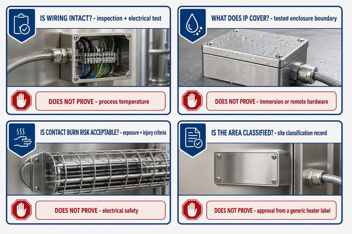
Electrical integrity, ingress protection, touch-safety assessment and hazardous-location approval answer different questions. A compliant decision identifies the responsible party, tested object, standard scope and installation instruction for each one. The OSHA rules cited below apply to United States workplaces; projects elsewhere must verify the destination country’s electrical and hazardous-location requirements. No single product label can replace wiring inspection, site classification, assembly testing or process-temperature review.
OSHA 1910.303(b)(2) requires listed or labeled equipment to be installed and used according to its instructions. Paragraph (b)(3) requires completed wiring to be free from short circuits and unintended grounds. Those duties remain separate from a temperature controller’s ability to hold a setpoint.
OSHA 1910.307 requires documentation for Class and Zone locations and for Class and Division areas established after August 13, 2007; it also says each room, section or area is considered individually. For Class I Zone classification and selection of equipment and wiring methods, OSHA requires supervision by a qualified registered professional engineer. A generic heater label or unsupported supplier statement is not the buyer’s site-classification record.
IEC explains that marketing terms such as “waterproof” or “water-resistant” are difficult to assess, while IEC 60529 grades enclosure resistance to dust and liquids. An IP code must therefore name the evaluated boundary: heater body, edge seal, lead exit, connector and controller are not automatically one tested object.
ASTM C1055 does not establish one universally safe surface temperature. It ties acceptable conditions to contact time, surface configuration and accepted injury level and limits its method to passive heated surfaces. The guide discusses 5 s for industrial contact and 60 s for consumer contexts inside that standard’s scope; neither value is a heater rating.
| Question | Controlling evidence | Owner | What it does not prove |
|---|---|---|---|
| Is wiring intact? | Inspection and electrical test plan. | Installer and site. | Process temperature. |
| What does IP cover? | Tested enclosure boundary. | Supplier/test body. | Immersion or remote hardware. |
| Is contact burn risk acceptable? | Exposure and injury criteria. | Designer/site authority. | Electrical safety. |
| Is the area classified? | Site classification record. | Employer/qualified professional. | Approval from a generic heater label. |
Commission the Heater With a Controlled Heat-Up Record
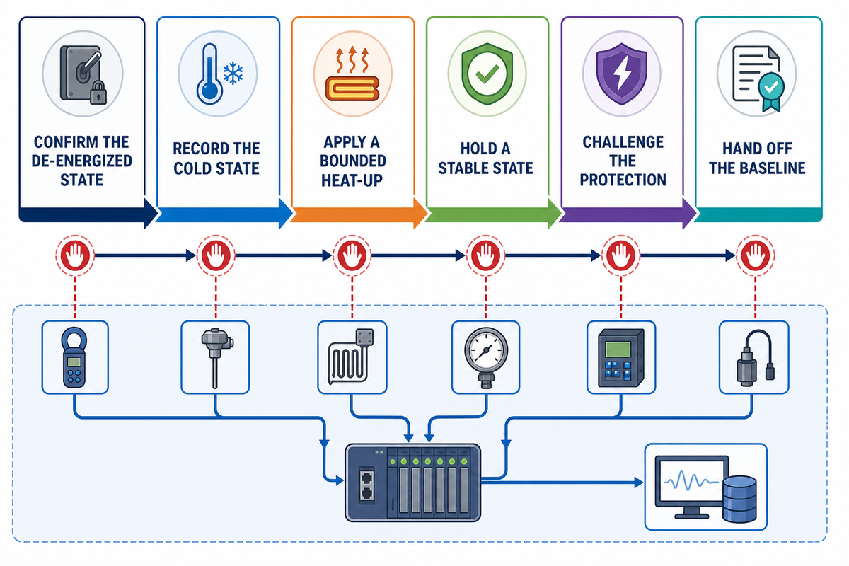
A controlled heat-up record turns installation assumptions into evidence. The record is not a universal heater test protocol. It adapts general commissioning discipline: define the objective, verify readiness, monitor a bounded functional test, analyze the result, correct one issue, retest and hand off the accepted configuration.
The U.S. Department of Energy describes a 4-step process: plan; investigate with functional tests and monitoring; implement with retesting and remonitoring; then hand off documentation and future test procedures. ASHRAE’s data-center framework likewise treats trended commissioning data as an operating baseline. Neither source mandates one silicone-heater sequence.
- Confirm the de-energized state — match the drawing, circuit identity, sensor, leads, attachment and insulation before power.
- Record the cold state — note ambient conditions and confirm each sensor reading is plausible for its measurement plane.
- Apply a bounded heat-up — use the released controller and protection settings while recording time, current or power, and critical temperatures.
- Hold a stable state — compare heater, substrate and process readings against the stated acceptance objective.
- Challenge the protection — verify the documented limit or alarm action without bypassing safety devices.
- Hand off the baseline — store the accepted configuration, readings, deviations and next inspection trigger.
A failed check does not justify increasing the setpoint. First identify whether the mismatch belongs to contact, load, sensor, control or protection. The next test changes one bounded variable so the result remains interpretable.
Diagnose Failures From Contact to Control
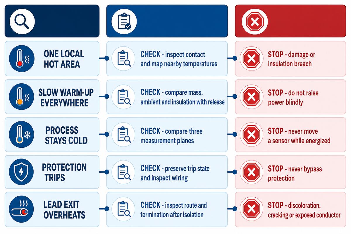
Troubleshooting should move from physical contact to electrical circuit, measurement and control before the heater is replaced. Forum searches supplied useful symptom language but no verified causes or failure rates. The table below is therefore a diagnostic framework: it proposes checks, not remote conclusions.
Why is a silicone heating pad not heating evenly?
Uneven heat can originate from a gap, local mass, circuit pattern, changed insulation, sensor position or load condition. Inspect the interface and compare multiple locations before changing power. A single controller value cannot identify which mechanism produced the temperature map.
Troubleshooting Check Sequence
| Symptom | Plausible mechanism | Discriminating check | Bounded next action | Stop condition |
|---|---|---|---|---|
| One local hot area | Gap or local heat-sink mismatch. | Inspect contact and map nearby temperatures. | Restore released contact condition. | Damage or insulation breach. |
| Slow warm-up everywhere | Load or loss exceeds design basis. | Compare mass, ambient and insulation with release. | Recalculate duty. | Do not raise power blindly. |
| Controller reaches setpoint; process stays cold | Sensor represents heater plane. | Compare three measurement planes. | Review feedback objective. | Never move a sensor while energized. |
| Rapid cycling | Sensor coupling or control tuning mismatch. | Trend sensor and output state. | Review controller setup. | Protection chatter or overheating. |
| No heat, circuit energized | Open circuit, termination or switching fault. | De-energize and test by released procedure. | Escalate electrical inspection. | Short, unintended ground or damaged lead. |
| Protection trips | Electrical fault or inappropriate protection. | Preserve trip state and inspect wiring. | Correct the documented fault. | Never bypass protection. |
| Lead exit overheats | Strain, sharp bend or termination issue. | Inspect route and termination after isolation. | Replace or reroute per released design. | Discoloration, cracking or exposed conductor. |
| Temperature drifts after insulation change | Outward heat loss changed. | Compare installed stack with baseline. | Reopen thermal review. | Do not reuse old settings. |
| Visible puncture or laminate damage | Mechanical or thermal damage. | No energized diagnostic. | Remove from service. | Immediate stop-work. |
When Silicone Rubber Is the Wrong Heater Construction
A silicone rubber heater is the wrong route when conductive contact cannot be maintained, free-air heating is the real duty, the environment exceeds the released construction, or the application needs removable coverage over a large body. Vacuum and outgassing-sensitive service also requires construction-specific test evidence outside this guide.
| Condition | Why this route becomes weak | Next question |
|---|---|---|
| Long process line | Duty may belong to a system method, not one pad. | Review industrial pipe process heating. |
| Frequent removal or irregular pipe component | Permanent contact can block service access. | Compare removable pipe heating blankets. |
| Full drum coverage | Container duty and access differ from a custom pad. | Review drum heating blankets. |
| Full tote coverage | The heated mass and outer losses need a container system. | Review IBC tote heaters. |
| Vacuum/outgassing-sensitive service | Air-side assumptions and material evidence change. | Require construction-specific vacuum test evidence. |
Freeze the Design Basis Before Requesting a Custom Configuration
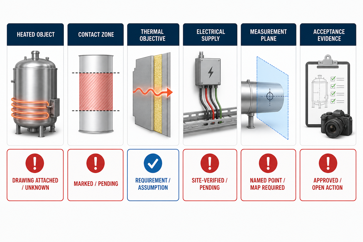
The final buyer task is not to choose a catalog number. It is to freeze the design basis: what is heated, where heat can flow, which temperature is controlled, which protections apply and which evidence will accept the assembly. Price, schedule, model release and quotation ownership remain on the commercial page.
Translate Catalog Vocabulary Into Evidence Requests
Flexible-heater catalogs use overlapping terms, and a familiar phrase can hide a different construction or evidence scope. Searchers use phrases such as silicone heat mat, silicone rubber heating pad, silicone rubber heater pad, silicone heating pad with thermostat and silicone heating pad 12V. These are query patterns—not released FlexBlanket specifications.
| Words a buyer may encounter | What to ask for | Evidence boundary |
|---|---|---|
| flexible silicone; flexible silicone heater; flexible silicone rubber heaters | Name the complete laminate, reinforcement and element. | “Flexible” is not a bend-radius or life rating. |
| silicone rubber heating; silicone rubber flexible; rubber flexible heater | Resolve search-language variants to one released construction. | Word order is not a technical distinction. |
| etched foil heaters; wire-wound silicone heaters; wire wound silicone rubber | Identify the circuit architecture and supplier design basis. | No universal performance winner. |
| resistance wire; heating circuits; circuit design | Request the approved resistance path, zones and terminations. | No inference from a generic diagram. |
| fiberglass; second layer; vulcanized; uncured; vulcanizing | Ask which material or process applies to the finished heater. | Raw-material words do not prove assembly performance. |
| watt densities; temperature range; high temperature | Bind values to heat sink, contact, ambient, control and test scope. | Family ranges are not application results. |
| uniform heat; temperature distribution; thermal performance | Define points, plane, load, soak time and acceptance method. | “Uniform” needs a measurement map. |
| temperature control; thermocouple; RTDs; thermistor | Name sensor type, location, wiring and controlled variable. | A sensor name is not a control result. |
| adjustable thermostat; bimetal; thermal fuses | Separate normal control from independent protection. | A setpoint does not prove protective action. |
| power cord; connector; grommet; abrasion | Define lead route, strain relief, bend clearance and environment. | Body ratings may exclude terminations. |
| mounting methods; field applied; magnetic mounting; lace | Identify the released attachment for the substrate and temperature. | Method names do not prove full contact. |
| detachable; permanent bond; heavy duty | Define removal frequency, load and service access. | Marketing adjectives need a test or drawing. |
| heater life; premature failure; rapid heating | Ask for conditions, duty cycle, failure definition and verification. | No unsupported life or speed promise. |
| industrial applications; application requirements; size and shape | Replace a broad use list with the actual heated-object record. | Industry name alone does not establish fit. |
| calculation tool; heaters can be designed; silicone rubber heaters provide… | Require inputs, assumptions, output units and the responsible reviewer. | Incomplete capability language is not evidence. |
| band heater; Kapton | Treat them as separate construction or product-family routes. | Do not target their dedicated head terms here. |
Do not fill a table with borrowed numbers
Values such as 120V, 450°F, 500°F or 1500W appear in competitor and catalog vocabularies. They are not approved FlexBlanket inputs in this article and are not recommendations. A number enters the design basis only when its source, unit, object and test scope are bound.
| Record field | Freeze before handoff | Evidence/status |
|---|---|---|
| Heated object | Material, mass and wall or plate geometry. | Drawing attached / unknown. |
| Contact zone | Heated area, cutouts and keep-outs. | Marked / pending. |
| Thermal objective | Start, target, ambient and allowed time. | Requirement / assumption. |
| Electrical supply | Nominal supply, current limit and switching. | Site-verified / pending. |
| Measurement plane | Heater, substrate or process variable. | Named point / map required. |
| Control and protection | Controller, switching and independent limit. | Function defined / pending. |
| Attachment | Permanent or removable method and contact. | Released method / review. |
| Insulation stack | Material, coverage, moisture and access. | Installed stack / assumption. |
| Environment | Dust, liquid, chemicals, vibration and area classification. | Site record / supplier evidence. |
| Acceptance evidence | Tests, readings, documents and responsible reviewer. | Approved / open action. |
Key takeaway
Freeze the heat sink, contact, measurement plane and protection scope before asking a supplier to release wattage or construction.
Once the record is complete, review FlexBlanket’s commercial page for silicone rubber heaters. That page owns product-family facts and the quotation handoff; this guide does not repeat them.
Frequently Asked Questions
Why can the same silicone rubber heater run at different temperatures on different surfaces?
The same electrical input can produce different installed temperatures because substrate conductivity, contact, geometry, insulation, airflow, sensing and controller logic change the heat-storage and heat-loss boundary around the heater.
The installed result depends on substrate conductivity, contact, geometry, insulation, airflow, sensing and controller logic. Identical electrical input can produce different surface temperatures when the heat sink or boundary conditions change. The sensor and controller then regulate one defined measurement variable. That complete chain—not the silicone laminate alone—determines whether the system holds its intended temperature.
What inputs belong in a silicone rubber heater design basis?
A usable design basis records the heated object, contact zone, start and target temperatures, ambient losses, electrical supply, measurement plane, protection, mounting, insulation, environment and acceptance evidence before a custom configuration is released.
Record the heated material and mass, usable contact area, starting and target temperatures, lowest ambient, airflow, insulation and allowed warm-up time. Add supply voltage and phase, switching method, sensor type and location, independent overtemperature action, attachment method, lead routing, ingress boundary and site-classification responsibility. Separate approved inputs from assumptions and open actions. The resulting record should be specific enough for a supplier to review the circuit pattern and for the site team to test the installed assembly without borrowing a family rating as an application guarantee.
How should wire-wound and etched-foil options be compared?
Compare wire-wound and etched-foil options by circuit routing, keep-outs, local heat profile, terminations, complete-laminate flexibility and the supplier’s approved drawing, not by assuming one architecture is universally superior.
Both architectures create a resistance path, but their patterning and production constraints differ. Review how the proposed route handles holes, cutouts, edges, local masses and lead exits. Ask for the complete laminate’s mechanical and thermal evidence, not a generic label. The available independent evidence does not support a universal ranking for precision, service life or cost, so the release decision belongs to the drawing and project-specific evidence.
How do the three temperature measurement planes differ?
The heater plane protects the laminate, the substrate plane represents the contacted object, and the process plane represents the downstream result; one sensor can be useful without representing all three.
A heater-plane sensor, substrate-plane sensor and process sensor answer different questions. Define the objective first, then verify the chosen point against other critical locations during commissioning. One sensor may be useful without representing the full temperature field.
What should a controlled heat-up record contain?
A controlled heat-up record should bind the approved configuration to ambient conditions, sensor identities, electrical input, time-stamped heater, substrate and process temperatures, protection actions, deviations and the accepted baseline.
Start with the de-energized drawing match and cold sensor readings. Record the bounded heat-up, stable hold and documented protection action without bypassing safety devices. If the result misses the objective, identify whether contact, load, sensing, control or protection owns the mismatch, change one variable and retest. Store the accepted settings, readings and inspection trigger for later comparison.
When is a removable heating blanket a better choice?
A removable heating blanket can be a better choice when equipment needs frequent service, the heated body is large or irregular, or the duty calls for full-container coverage instead of a bonded surface element.
This is a method decision, not proof that one product family is always superior. The final route still depends on thermal duty, geometry, contact, control, environment and inspection access. Use the verified alternative pages for specific commercial options.
What belongs in a design review before requesting a custom heater?
Freeze the thermal, electrical, mechanical, control and evidence boundaries.
Record the heat sink, geometry, contact zone, target and ambient conditions, supply, measurement plane, controller and protection, attachment, insulation, environment and acceptance evidence. Keep assumptions and open actions visible, then hand the validated design basis to the commercial solution page.
Review Your Heater Design Basis
Bring the heated-object drawing, contact zone, thermal objective, measurement plane, electrical supply and protection requirements to the engineering discussion.
How this guide was prepared
The preparation method for this guide separates authority evidence, peer-reviewed mechanisms, first-party product context and editorial decision frameworks. The guide excludes named-customer claims, competitor product values and universal application settings because the available evidence does not support transferring them to a buyer’s installation.
References & Sources
- Thermal Control — NASA Small Spacecraft Systems Virtual Institute
- Fire Dynamics: Heat Flux — National Institute of Standards and Technology
- IEEE/IEC 62395-1:2024 — IEEE Standards Association
- Thermal Management of Serpentine Flexible Heater — Micromachines
- Design and Thermal Analysis of Flexible Microheaters — Micromachines
- Printed Temperature Sensor Array for High-Resolution Thermal Mapping — Scientific Reports
- 29 CFR 1910.303 — Occupational Safety and Health Administration
- 29 CFR 1910.307 — Occupational Safety and Health Administration
- Ingress Protection Ratings — International Electrotechnical Commission
- ASTM C1055-20 — ASTM International
- Commissioning Process for Federal Facilities — U.S. Department of Energy
- Commissioning & Performance Validation — ASHRAE