Get in touch with FlexBlanket Company

Updated August 2026
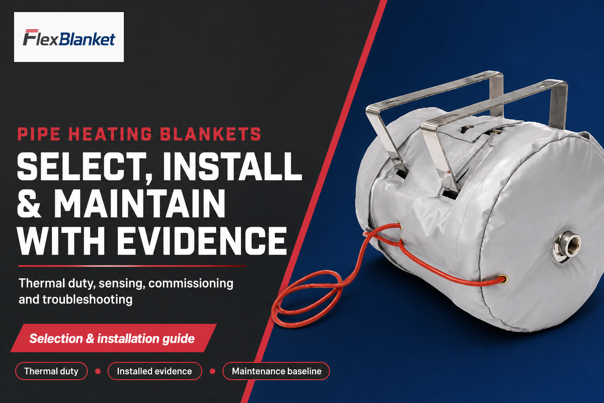
Pipe Heating Blankets are removable flexible heating assemblies used around pipes and components for freeze protection, temperature maintenance, or controlled heat-up. Those duties are not interchangeable. Reliable selection begins with the pipe, fluid, ambient exposure, insulation, access plan, sensor objective, and commissioning evidence, not with a catalogue temperature printed beside a blanket family.
That distinction matters on an industrial line. Short water-line wraps may be wrong for a valve body, a hazardous location, a dry plastic pipe, or a process stream with a narrow allowable temperature band. Engineering and maintenance teams need a way to define the job before they request a product configuration.
Direct answer
Pipe heating blankets are selected by thermal duty, contact geometry, insulation, control objective, and verification plan. Blanket wattage or maximum heater temperature alone can’t establish pipe-wall or fluid performance.
Quick Specs for the Selection Brief
| Duty | Freeze protection, temperature maintenance, or controlled heat-up |
| Geometry | Outside diameter, heated length, fittings, supports, penetrations, and removal direction |
| Environment | Minimum ambient, wind, moisture, chemicals, washdown, and area classification |
| Thermal system | Pipe and fluid properties, insulation thickness, jacket, target temperature, and heat-up time |
| Control | Sensor objective, location, controller behavior, alarms, and overtemperature action |
| Evidence | Installation record, cold baseline, heat-up trend, stable-state readings, and maintenance ownership |
Key points
- A 5-layer decision chain prevents wattage selection from outrunning the evidence.
- Removable blankets and permanent heat trace win under different access and geometry conditions.
- Insulation, moisture control, inspection access, and reinstatement belong to one system.
- Commissioning must prove circuit availability and local pipe response, not merely controller power.
Start With the Thermal Duty, Not the Blanket
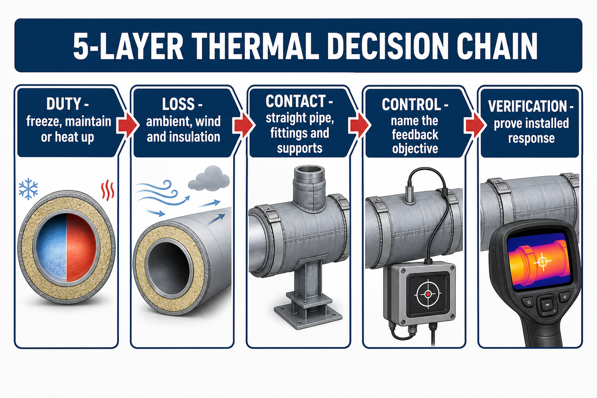
Outside diameter alone can’t size a pipe heating blanket. Freeze protection, steady temperature maintenance, and scheduled heat-up impose different loads for water, chemicals and other fluids, while wind, insulation, pipe conductivity, supports, and acceptable warm-up time change the result. Designers must determine how much heat the installed system loses under its stated boundary conditions.
ORNL’s MEASUR pipe model calculates heat loss per unit length from cylindrical pipe and insulation resistance, convection, radiation, ambient conditions, and wind. Its solver updates surface temperature until the heat-loss change is below 0.0001 W/m or 30 iterations are reached. That detail shows why a universal W/ft value omits variables that drive the answer.
Five linked layers form the 5-Layer Thermal Decision Chain. Its logic synthesizes the ORNL model, insulation guidance, standard scope, first-party application categories, and commissioning evidence; no standard publishes this exact table.
| Layer | Decision record | Evidence to collect | Limitations / Not suitable for |
|---|---|---|---|
| Duty 1 | Freeze protection | Minimum ambient, exposure duration, fluid freezing behavior | Does not establish process temperature |
| Duty 2 | Temperature maintenance | Normal flow, target band, fluid and pipe limits | Does not establish heat-up time |
| Duty 3 | Controlled heat-up | Starting temperature, mass, time allowance, allowable ramp | Not a steady-state shortcut |
| Loss 1 | Ambient and wind | Minimum °C/°F, wind m/s, indoor/outdoor exposure | Weather history is not a site guarantee |
| Loss 2 | Insulation and jacket | Material, thickness mm, joints, vapor/weather barrier | Dry-laboratory conductivity is not installed U-value |
| Contact 1 | Straight pipe contact | OD mm, length m, closure and lead direction | Not transferable to fittings |
| Contact 2 | Fittings and thermal bridges | Valve, flange, support, penetration, small-bore line | A diameter-only wrap can leave gaps |
| Control | Feedback objective | Heater, pipe-wall, or process temperature; alarm and trip action | One sensor cannot represent every location |
| Verification | Installed response | Cold baseline, heat-up trend, stable readings, circuit availability | Catalogue data is not acceptance evidence |
For an illustrative brief, a team might record a 60.3 mm outside diameter, a 10 m heated length, a 20 °C target, a −20 °C design ambient, a 5 m/s wind case, and 50 mm of insulation. Those numbers are inputs, not an answer. Next, run a condition-bound calculation and review pipe, fluid, insulation, power, sensor, and protection limits.
“The U-value … characterizes the thermal performance of a system as opposed to a homogeneous material.”
Decision: keep the duty unresolved until all five layers have an owner. An upstream industrial pipe process heating page can frame the wider method decision, but each application still needs project-specific calculations.
Choose a Blanket or Heat Trace
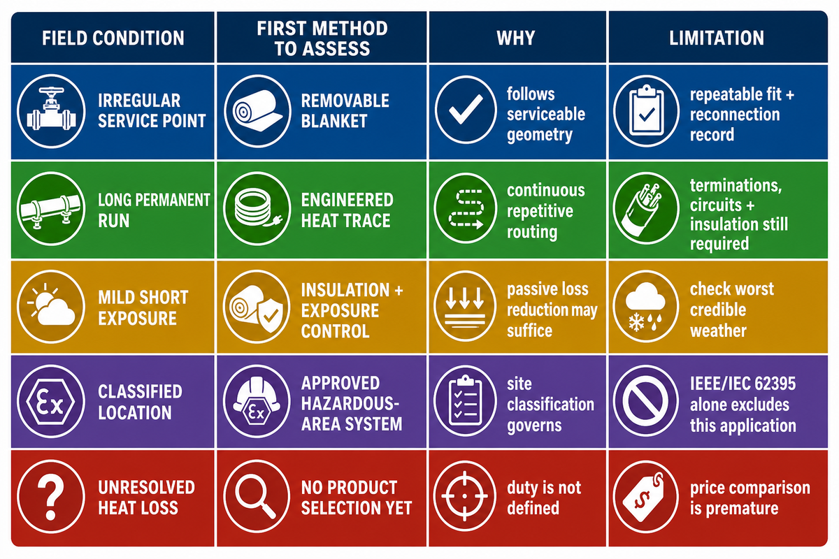
Removable blankets and permanent heat trace solve different installation problems. Blankets can suit irregular or serviceable components when a shaped assembly and repeatable removal plan are required; cable trace can suit long, repetitive pipe runs. Insulation or non-electric freeze-protection methods may also win when power availability, process criticality, or access changes the risk.
A ThermOmegaTech-authored article published by Plant Engineering routes methods by climate severity, vulnerable-area criticality, power availability, and exposure. Its analysis says insulation isn’t always enough and electric systems remain vulnerable to power failure or insufficient design. Because the author works in marketing for a freeze-protection supplier, this evidence supports a conditional route only, not a claim that one product family is best.
| Field condition | First method to assess | Why | Limitations / Not suitable for |
|---|---|---|---|
| Short irregular valve body | Shaped removable blanket | Coverage can follow geometry and permit service removal | Requires a repeatable fit and reconnection record |
| Long straight permanent run | Engineered heat trace | Continuous routing can fit repetitive geometry | Terminations, circuits, insulation, and maintenance remain required |
| Frequent inspection point | Removable cover or inspection port | Access is designed into maintenance | Weather barrier must be restored after work |
| Power-loss consequence is high | Redundant or non-electric strategy | Electric heat disappears with circuit loss | Needs process and site-level risk review |
| Mild, short cold exposure | Insulation and exposure control | Passive loss reduction may be sufficient | Must be checked against worst credible weather |
| Narrow process temperature band | Engineered controlled system | Feedback, zoning, and alarms carry the decision | A preset consumer wrap is not equivalent |
| Potentially explosive atmosphere | Approved hazardous-area system | Site classification and marked equipment govern | IEEE/IEC 62395 alone excludes this application |
| Empty or dry plastic pipe | Product-specific review | Heat sink and material limits can change sharply | Never infer permission from another blanket family |
| Unresolved heat loss | No product selection yet | The duty is not defined | Price comparison is premature |
This table is a buyer synthesis, not a standard-prescribed matrix. It doesn’t replace the interactive tool already published on the site; teams needing a structured input review can compare pipe heating methods without copying that tool into this article.
Search terms that describe different heating products
Search results mix industrial heating equipment, consumer freeze wraps, PVC tools, cable trace, and cure products under similar names. Treat each phrase as a discovery clue, not proof that two products share electrical approval, temperature range, construction, or permitted use.
Queries such as “industrial heating blanket for pipe,” “heat blanket for PVC pipe,” “outdoor heat blanket for pipes,” and “heat trace blanket” can describe different product families. Related searches such as “Best pipe heating blankets,” “Electric pipe heating blankets,” and “Heat blanket for PVC” still require the same scope check before an industrial buyer treats the results as comparable.
| Product type / search wording | Possible meaning | Evidence boundary |
|---|---|---|
| industrial heating blankets / pipe heating wrap / heated pipe wraps | Broad industrial surface heating category | Needs exact construction, duty, approval, and instructions |
| water pipe heat blanket / outdoor water / faucet | Consumer or light-commercial freeze product | Does not establish industrial process suitability |
| heat tape / pipe heat tape / heat cable | Cable-style trace heating | Cable routing and termination rules differ from a blanket |
| self-regulating pipe heating / built-in / adjustable | A control or element behavior claim | Verify exact model, sensor, setpoint, and response |
| aluminum foil / 120V / power cord | Construction and supply descriptors | Do not infer listing, process rating, or outdoor approval |
| cure / thaw | A timed process duty, not simple freeze holding | Requires its own ramp, soak, and acceptance specification |
| hose / tubing bundles / pipeline | Different geometry and movement constraints | One pipe diameter cannot represent the assembly |
| even heat / distribute / covered surface | Temperature-uniformity language | Needs a measurement method, locations, load, and tolerance |
| weatherproof / durable / rugged / easy-to-use | Marketing descriptors | Replace with test scope, material, enclosure, and maintenance evidence |
| easy to install / wraps around / wrap-around | Installation convenience claim | Does not waive trained connection, fit, sensor, or protection work |
| ETL / ETL certified / UL / CSA safety standards | Listing or certification language | Require the exact model, standard, mark, file, and destination scope |
| preset 90°F / dependable freeze protection / safety features | Product-specific performance or safety wording | Never transfer it to another product, pipe, fluid, or site |
For cold conditions, the real goal may be to maintain flow, prevent frozen pipes, protect pipes from freezing, or limit downtime. Those outcomes require measured heat-up, power consumption, overheat response, insulation, and circuit availability. Category language can’t stand in for installed evidence.
Treat Insulation, Moisture, and Access as One System
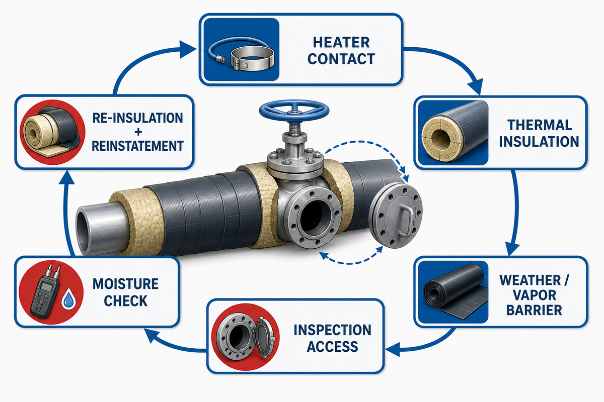
Whichever heating method is chosen, heater output, thermal insulation, weather or vapor barrier, drainage path, inspection access, and reinstatement quality form one system. Removable access can be a deliberate advantage at valves, fittings, and flanges, but every removal opens a second task: restore contact, insulation, joints, identification, and the water-shedding outer layer correctly.
NIA’s installation guide describes removable insulation covers or inspection ports as access provisions for periodic inspection, especially at valves, fittings, and flanges where leakage is more likely. It also calls for re-insulation in the same manner as the original installation unless the damage shows that the prior system was improper or its materials are outdated. Access is therefore a designed maintenance feature, not proof of moisture protection.
AMPP’s 2025 CUI guidance identifies water intrusion as the leading cause of corrosion under insulation and recommends visual checks, access provisions, resealing, jacket repair, coating review, and risk-based inspection. A peer-reviewed CUI review describes moisture beneath insulation and the inspection sequence of removal, testing, and reinstallation.
Do
- Record removal direction and closure order.
- Inspect for staining, jacket damage, and wet insulation.
- Restore identification, joints, and water-shedding layers.
- Compare post-work sensor readings with the baseline.
Don’t
- Treat removability as proof of moisture protection.
- Hide a wet or damaged area under a reinstalled blanket.
- Add insulation without checking the heater instructions.
- Assume the old sensor position was representative.
Can I add insulation to help a pipe heating blanket?
Insulation can reduce heat loss, but adding it changes the installed thermal system and may alter heater temperature, moisture behavior, and access. Supplier instructions and the approved heat-loss review must permit the construction. Extra insulation isn’t a harmless afterthought, and one vendor’s prohibition or permission can’t be transferred to another product.
Fit Straight Pipe, Valves, Flanges, and Supports
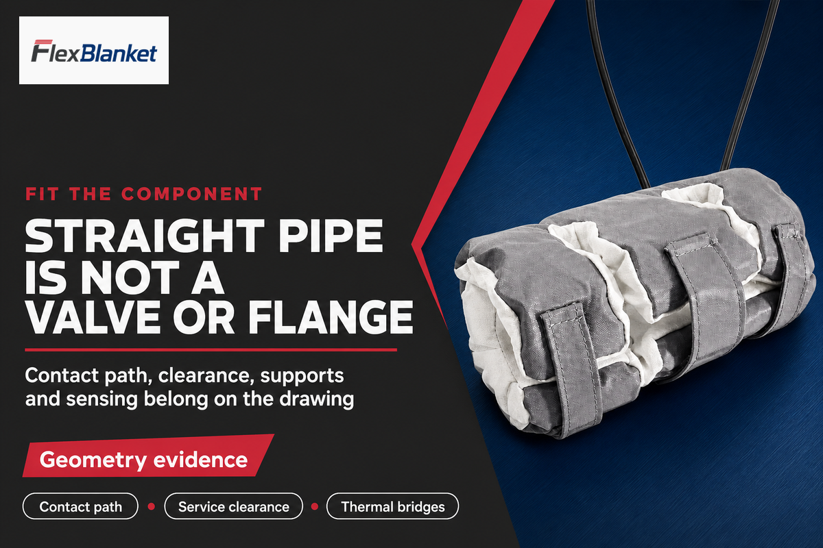
Straight pipe, bends, valves, flanges, supports, penetrations, and small-bore sensing lines do not present the same contact or heat-loss path. Support brackets can act as local heat sinks; flanges can interrupt contact; penetrations can restrict closure. Geometry must be recorded at the component level before coverage is selected.
Published application US20130104988A1 describes a semiconductor fluid-line heater jacket using spacers, bends, separate thermocouple zones, and removable closures. The application names Andrew M. Yednak III and Frederick L. Pettinger Jr. as inventors, was filed by ASM America Inc, and currently lists ASM IP Holding BV as the assignee; it is not FlexBlanket technology. Its dimensions or temperature values do not transfer here. Its useful lesson is narrower: contact path, bends, zoning, and sensing are intentional design variables.
At a pipe support, the blanket drawing should show where heat contact stops, where insulation is compressed or interrupted, and how the support conducts heat away. At a flange or valve, record fasteners, stems, packing access, actuator clearance, removal direction, and lead or sensor routing. Photos help orient the drawing, but dimensions and service clearances remain the release inputs.
Use the site’s application-fit review when the component cannot be described by diameter and length alone.
Place the Sensor for the Temperature You Need to Control
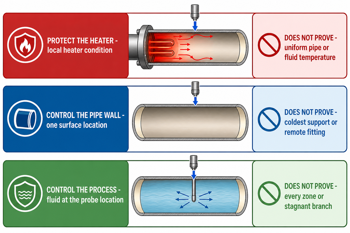
Sensor placement should follow the feedback objective. Sensors near the heating element can represent heater conditions; pipe-wall sensors represent one surface location; process probes represent fluid only at their own points and response times. Control documents must name which temperature governs normal control, alarm, and shutdown decisions.
NRC LER 99-001-00 gives this issue operational weight. Its corrective actions called for clearer temperature-element placement, wire configuration, insulation requirements, and use of a pyrometer. Those corrective actions show why control indication should be checked against independent local-temperature evidence.
| Objective | What the sensor may represent | What it does not prove |
|---|---|---|
| Protect the heater | Local heater or sheath condition | Uniform pipe-wall or fluid temperature |
| Control the pipe wall | One attached surface location | Coldest support, remote fitting, or bulk fluid |
| Control the process | Fluid at the probe location and response time | Every surface zone or stagnant branch |
Where should the temperature sensor go?
Sensor placement should represent the documented control objective and remain repeatable after service. Record the attachment method, insulation around it, distance from the element or thermal bridge, cable route, alarm logic, and reference measurement. Commissioning should compare the sensor with independent readings at vulnerable locations rather than assuming one point covers the line.
Install Without Gaps, Overlap, or Trapped Damage
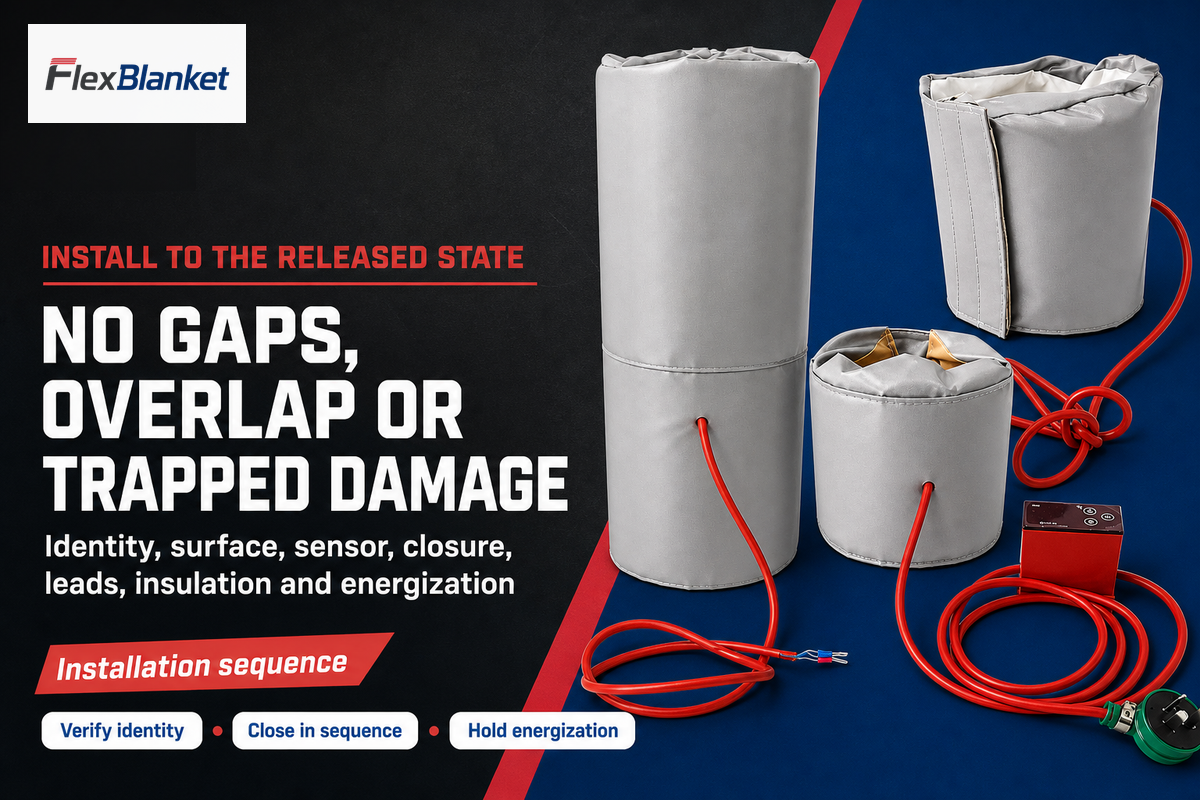
Installation should preserve the approved contact pattern, closure sequence, lead exit, sensor location, insulation system, electrical protection, and removal path. Cutting, overlap, burial, stacking, sharp folding, or operation on an empty pipe must never be inferred from another heater family. Permission and limits belong to the supplied model’s instructions and project documents.
Active IEEE/IEC 62395-2:2024 guidance covers system design, installation, maintenance, and repair. Its scope also says surface heaters are assembled or terminated according to manufacturer instructions and that critical connection or termination work is for trained personnel under qualified supervision.
- Verify identity. Match the blanket, controller, sensor, circuit, drawing, and location tag.
- Inspect the surface. Remove debris, sharp edges, damage, and moisture that would change contact.
- Set the sensor. Attach it in the documented orientation before closing the blanket.
- Close in sequence. Keep the intended contact path without unapproved overlap or bunching.
- Route leads. Protect exits from strain, abrasion, hot surfaces, standing water, and service movement.
- Restore insulation. Rebuild joints and the weather or vapor barrier according to the approved construction.
- Hold energization. Release power only after the electrical and mechanical checks are signed.
Use the 4-State Commissioning Baseline
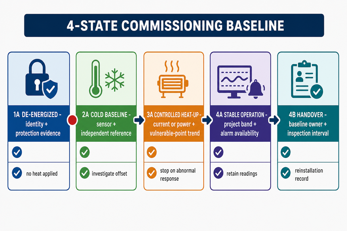
Commissioning should prove both thermal response and continuing circuit availability. Four states, de-energized, cold, controlled heat-up, and stable operation, create a record that links installation, sensor identity, protection, alarms, current or power, and local pipe readings. Controller displays alone can’t prove the coldest segment or the alarm path remains protected.
Four defined states form the 4-State Commissioning Baseline, a practical synthesis of the IEEE/IEC 62395-2 application-guide scope and the NRC heat-tracing event. Acceptance values come from the approved design; this table defines evidence fields, not universal pass numbers.
| State | Record A | Record B | Release boundary |
|---|---|---|---|
| 1A De-energized | Correct product, circuit, controller, sensor, drawing, and location | Continuity/insulation/protection evidence required by the design | No heat applied yet |
| 1B Availability | Fuse, disconnect, circuit status, alarm path, and instrumentation available | Loss-of-power or failed-alarm response documented | Temperature evidence cannot replace this check |
| 2A Cold baseline | Ambient °C/°F and sensor reading before heat | Independent reference readings at vulnerable points | Unexpected offset is investigated |
| 2B Mechanical baseline | Closures, contact, support gaps, penetrations, leads, and insulation | Photos or marked drawing preserve reinstallation state | No hidden wet or damaged insulation |
| 3A Controlled heat-up | Elapsed min, current A or power W, controller and reference temperatures | Trend at straight run, fitting, support, and remote point | Stop on abnormal rise, trip, smell, damage, or alarm |
| 3B Protection response | Alarm, limit, trip, and reset behavior | Authorized response and fail state recorded | No safety-integrity claim without evidence |
| 4A Stable operation | Setpoint, cycling pattern, pipe and process readings over stated time | Current/power and alarm availability remain present | Acceptance uses the project band |
| 4B Handover | Baseline, owner, inspection interval, spare/repair route | Removal and reinstallation record location | Unresolved deviations stay open |
Training-only commissioning record
The values below are fictional inputs chosen to show how a filled record links evidence. They aren’t FlexBlanket test data, a design recommendation, or permission to use any setpoint.
- Geometry and duty: 60.3 mm OD, 10 m heated length, 20 °C target, −20 °C ambient, 5 m/s wind, and 50 mm insulation.
- Illustrative resistive circuit: 230 V × 6.2 A = 1,426 W, or 1.426 kW; measured real power and controller behavior still govern.
- Cold baseline: sensor −18.6 °C, reference −18.4 °C, difference 0.2 °C before energization.
- Heat-up trend: −8 °C at 10 min, 1 °C at 20 min, 7 °C at 30 min, 16 °C at 60 min, and 19 °C at 90 min.
- Stable-state example: 20 ± 1 °C for 30 min with current, alarm path, and vulnerable-point readings still present.
Read the 7-Symptom Heat-Fault Casebook
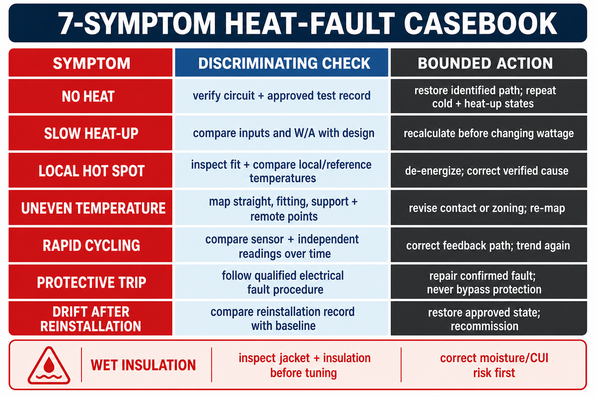
Troubleshooting should begin with a symptom, then test one discriminating mechanism before making one bounded change. Cold pipe conditions can come from lost power, poor contact, wet insulation, a misplaced sensor, a local support heat sink, inadequate duty, or process change. Replacing the blanket first can hide the original failure and destroy evidence.
Electrical practitioners often start with terminations, ground-fault paths, thermostat behavior, and pipe state when a traced line fails. Forum discussion supplies field vocabulary, not universal repair instructions. The NRC corrective-action record identifies sensor placement, wiring, insulation, and pyrometer measurement as distinct corrective-action topics that can inform troubleshooting within approved site procedures. Electrical testing and repair remain within the site’s approved procedures and qualified-person boundaries.
| Symptom / boundary | Plausible mechanisms | Discriminating check | Bounded action and verification |
|---|---|---|---|
| 1 No heat | Lost supply, open circuit, controller state, disconnected lead | Verify circuit and approved electrical test record | Restore the identified path; repeat cold and heat-up states |
| 2 Slow heat-up | Understated loss, changed ambient, wet insulation, process load | Compare current inputs and W/A readings with the design | Recalculate before changing wattage |
| 3 Local hot spot | Overlap, bunching, air gap, poor heat sink, sensor bias | Inspect fit and compare local/reference temperatures | De-energize and correct only the verified installation cause |
| 4 Uneven temperature | Support bridge, flange gap, sensor placement, insulation breach | Map readings at straight, fitting, support, and remote points | Revise contact or zoning; re-run the map |
| 5 Rapid cycling | Sensor too close to element, loose attachment, control tuning | Compare sensor and independent pipe readings over time | Correct the documented feedback path, then trend again |
| 6 Protective trip | Ground fault, damaged lead, termination, moisture, overload | Follow the site’s qualified electrical fault procedure | Repair the confirmed fault; never bypass protection |
| 7 Drift after reinstallation | Changed fit, sensor, closure, insulation, or circuit connection | Compare the reinstallation record with the baseline | Restore the approved state and recommission |
| Boundary: wet insulation | Water ingress or damaged weather barrier | Inspect jacket and insulation condition before thermal tuning | Correct moisture/CUI risk first; do not mask it with more heat |
Why is the blanket not getting hot enough?
Low temperature doesn’t identify a single cause. Confirm power and protection availability, present current or power, controller state, sensor position, blanket contact, insulation condition, ambient exposure, pipe contents, and local thermal bridges. Compare findings with the approved duty before changing a setpoint or heater. One confirmed mechanism should lead to one bounded correction and a fresh commissioning trend.
Plan Seasonal Inspection Before Cold Weather
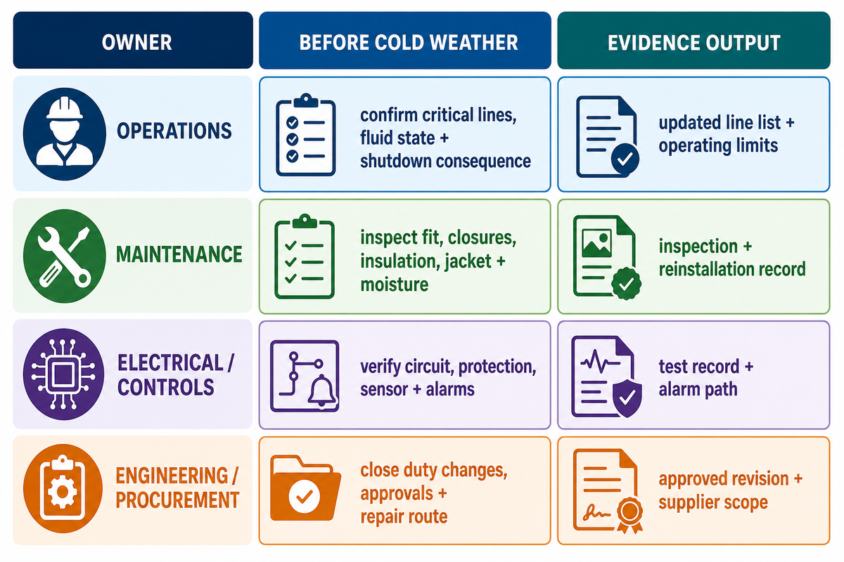
Seasonal readiness for outdoor pipes should be scheduled before the exposure arrives, not inferred from a market forecast. DataForSEO returned a 12-month series with strong seasonality for the pipe-heating query cluster but no prior-year matching quarter for a valid year-over-year label. Defensible planning ties inspection timing to local climate, criticality, and failure consequence.
The supplier-authored Plant Engineering article recommends identifying freeze-vulnerable areas and assessing both climate severity and water-supply criticality. In its sprinkler-system context, Missouri Department of Health guidance on frozen piping directs facilities to check displaced attic insulation and install temperature sensors for cold spots; its listed-equipment restrictions remain specific to that application. Inspection scope should cover displaced insulation, damaged weather barriers, closures, leads, sensors, circuit and alarm availability, backup-power assumptions, commissioning records, and access to valves or supports. Facilities with several exposure zones may need more than one protection method.
| Owner | Before cold weather | Evidence |
|---|---|---|
| Operations | Confirm critical lines, fluid state, normal flow, and shutdown consequences | Updated line list and operating limits |
| Maintenance | Inspect fit, closures, insulation, jacket, supports, and moisture signs | Inspection and reinstallation record |
| Electrical/controls | Verify circuit, protection, sensor, alarms, and loss-of-power response | Test record and alarm path |
| Engineering/procurement | Close duty changes, material limits, approvals, and spare/repair route | Approved revision and supplier scope |
Keep Safety and Approval Boundaries Explicit
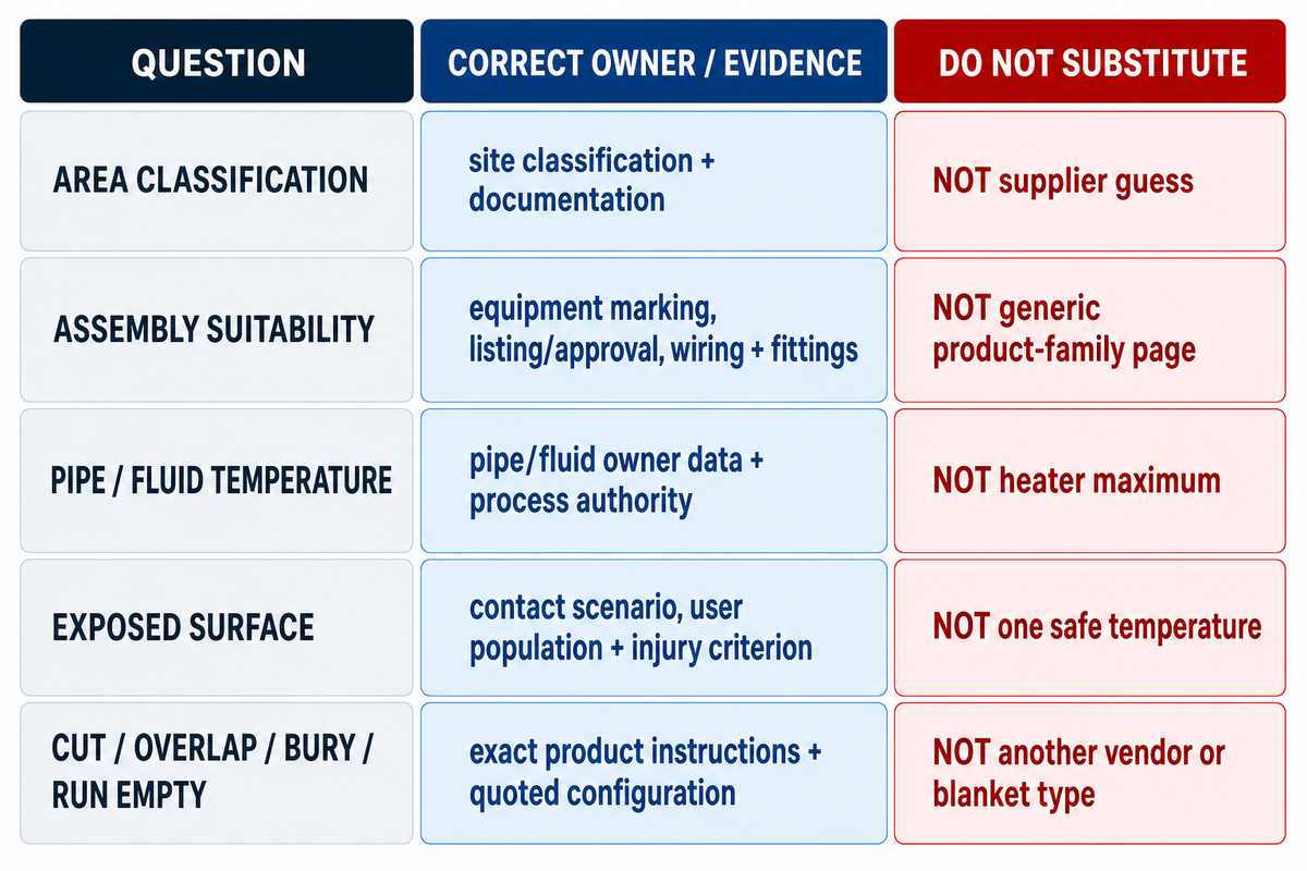
Thermal selection can’t replace electrical, process, and site approvals. Site teams own hazardous-area classification and documentation; equipment packages must match that location; pipe owners supply material and fluid limits; and surface-contact assessments depend on contact time and injury criteria. Product temperature, enclosure rating, and certification are separate evidence objects.
OSHA 1910.307 requires hazardous locations to be classified and documented, with equipment, wiring methods, and installations suitable for the classified location. Approval extends beyond the blanket surface: protection technique, fittings, wiring, grounding or bonding, markings, ambient range, and operating temperature can all carry system-level consequences.
ASTM C1055-20 says determining one universally safe surface temperature is beyond its scope. ASTM contrasts a proposed 60 s consumer contact with a 5 s industrial contact and notes that injury above 70 °C on metallic surfaces can occur almost instantly. Those examples show why a maximum heater rating cannot be relabeled as “touch safe.”
IEEE/IEC 62395-1 and 62395-2 explicitly exclude potentially explosive atmospheres. Separately applicable hazardous-area standards and an approved installation route are required. Accordingly, no FlexBlanket certification for a classified location is claimed, and no ingress rating is treated as proof of washdown, immersion, or third-party testing.
| Question | Owner/evidence | Do not substitute |
|---|---|---|
| What is the area classification? | Site classification and documentation | Supplier guess |
| Is the assembly suitable there? | Equipment marking, listing/approval, wiring and fittings | Generic product-family page |
| Can the pipe or fluid accept the temperature? | Pipe/fluid owner data and process authority | Heater maximum |
| Is the exposed surface acceptable? | Contact scenario, user population, injury criterion, guard/insulation design | One “safe” temperature |
| Can it be cut, overlapped, buried, or run empty? | Exact product instructions and quoted configuration | Another vendor or blanket type |
Where the Guide Hands Off to a Product Specification
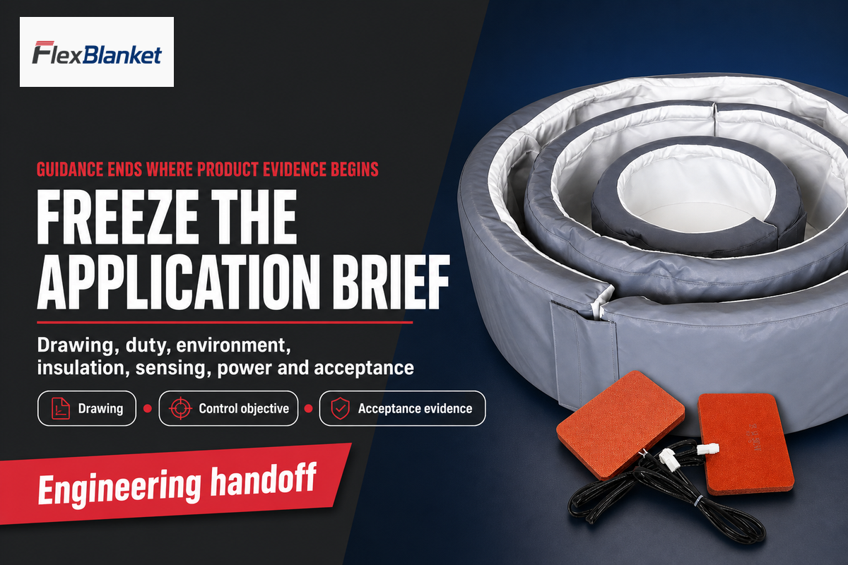
Guidance ends where product evidence begins. Once duty, geometry, environment, insulation, sensor objective, electrical boundary, and acceptance method are fixed, the supplier can return a construction, power basis, control package, limits, documentation scope, and quotation. Commercial fields remain on the existing solution page rather than being duplicated here.
Key takeaway
A blanket quote is comparable only after Duty, Loss, Contact, Control, and Verification are all defined.
Review FlexBlanket’s pipe heating blanket configuration options after the engineering brief is ready. Teams that need a structured handoff can also prepare the final application brief.
Need a project-specific review?
Send the pipe drawing, thermal duty, environment, insulation, control objective, power supply, and acceptance requirements. FlexBlanket can review the supplied inputs without treating this guide as a product approval.
Pipe Heating Blankets FAQ
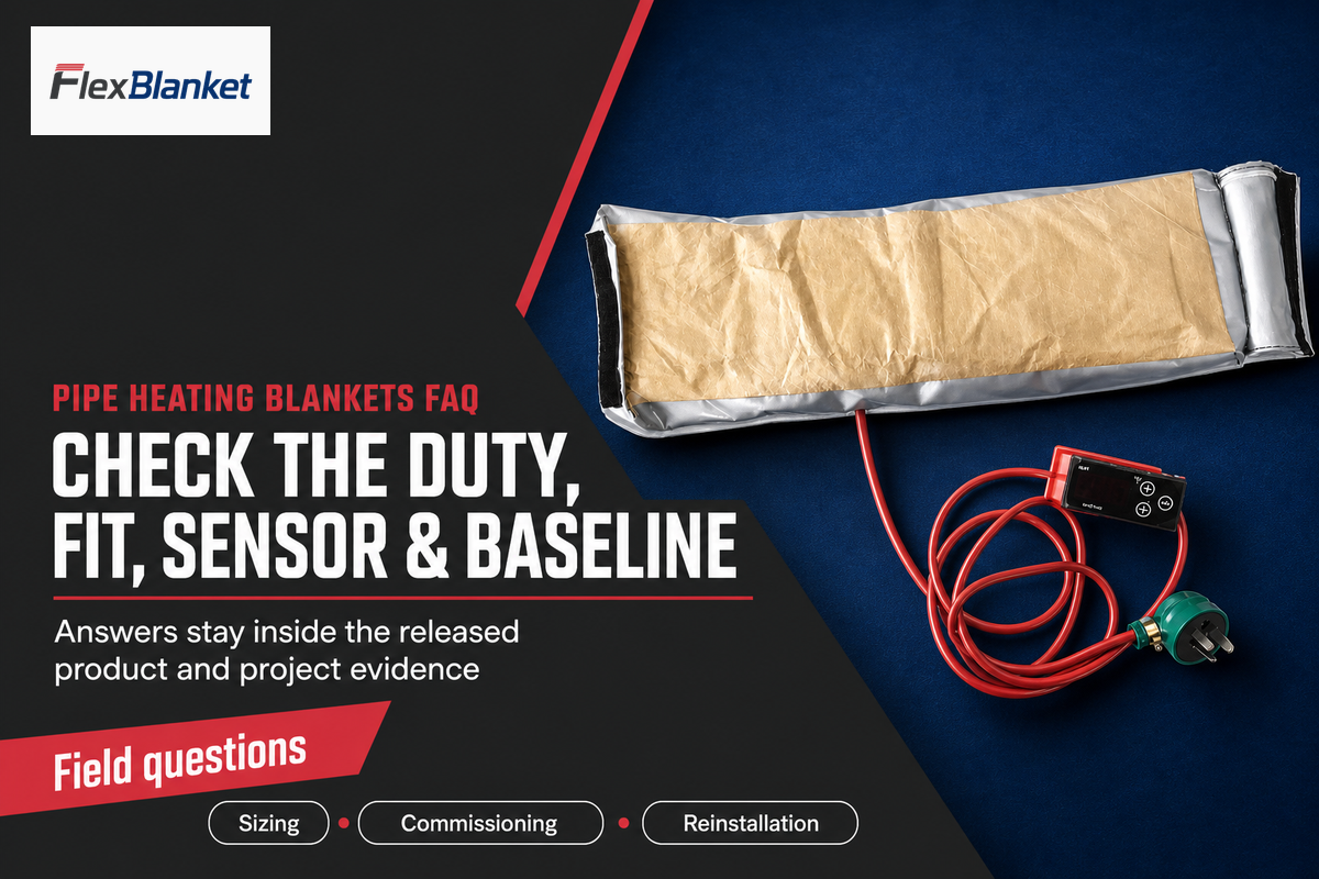
How do you size a pipe heating blanket?
Size a pipe heating blanket from the installed heat-loss duty, then match geometry, insulation, sensor objective, available power, and verification; do not treat one family-level W/ft rating as the installed result.
Record pipe OD and length, pipe and fluid properties, target temperature, minimum ambient, wind, insulation, exposure, available power, and allowable heat-up time. Use those inputs in a condition-bound heat-loss calculation, then verify that the proposed contact pattern, sensor objective, controller, protection, and commissioning record match the duty. A family-level W/ft figure cannot complete that review.
Can a pipe heating blanket work without insulation?
A blanket may produce heat without added insulation, but only a heat-loss calculation and the exact product instructions can show whether the pipe will hold its target safely.
Insulation changes steady heat loss, warm-up time, exposed-surface conditions, and moisture behavior. The approved product construction must state whether separate insulation is required, permitted, or prohibited. The weather barrier and inspection plan also matter. Never add insulation by copying another vendor’s installation; doing so can change heater temperature and overtemperature risk.
Where should the temperature sensor be placed?
Place the sensor where it represents the temperature named in the control objective, then verify vulnerable pipe locations independently during commissioning instead of assuming one point represents the line.
A sensor close to the element may protect the heater yet miss a cold pipe segment. A pipe-wall sensor measures one surface location and may lag the fluid. A process probe represents its own point and response time. Document attachment, insulation, distance from heat sources or supports, alarm logic, and independent commissioning readings.
What should be recorded during pipe heating blanket commissioning?
Record the installed state, cold baseline, controlled heat-up, stable-state readings, circuit availability, alarm response, sensor locations, and every unresolved deviation with named owners before acceptance.
Photograph fit, closures, contact gaps, leads, sensors, insulation, and vulnerable fittings. Record reference temperature, voltage, current or power, controller output, alarm and trip checks, and readings at straight pipe, supports, flanges, and remote points. State the acceptance band and test duration before energization. Include the component and blanket IDs, drawing revision, operator, date, ambient condition, pipe contents, controller settings, protection-test results, measuring-instrument IDs, and sign-off owner. Store photographs and trend files with the record so a future removal, repair, or cold-weather event can be compared against the same acceptance basis. The record should let maintenance teams distinguish the approved baseline from later drift.
Why can pipe temperature drift after blanket reinstallation?
Temperature can drift when fit, contact, closure sequence, sensor position, insulation, moisture condition, or circuit connection no longer matches the commissioned baseline and acceptance record.
Compare the reinstalled blanket with the original drawing, photographs, sensor attachment, insulation record, and stable-state trend. Check for shifted closures, new gaps, compressed or wet insulation, a moved sensor, a changed support heat sink, and altered electrical readings. Restore the approved state, correct one confirmed mechanism, and recommission before accepting a new setpoint.
Can a pipe heating blanket be used on PVC or another plastic pipe?
Plastic-pipe use requires the pipe’s own documented temperature and pressure envelope, fluid and operating state, plus a compatible heater, sensor, setpoint, alarm, and trip design.
Separate PVC conduit-bending blankets from freeze-protection products. Confirm resin, wall, pressure, fluid, filled or empty state, contact, sensor, insulation, setpoint, alarm, and trip action; heater maximum never replaces the pipe service limit.
Why This Guide Separates Method from Product
FlexBlanket manufactures industrial electric heating blankets and flexible heating solutions. This article deliberately keeps public engineering sources, first-party product scope, and project-specific approval separate. It uses the existing pipe-heating page only for the commercial handoff and doesn’t claim private test data, certifications, customer outcomes, or universal application limits.
References & Sources
- Insulated Pipe Reduction Calculator Documentation Oak Ridge National Laboratory
- Thermal Insulation Basics National Insulation Association
- IEEE/IEC 62395-1:2024 IEEE Standards Association
- IEEE/IEC 62395-2:2024 IEEE Standards Association
- Understanding Corrosion Under Insulation Association for Materials Protection and Performance
- A Review of Corrosion under Insulation Metals
- Licensee Event Report 99-001-00 U.S. Nuclear Regulatory Commission
- Determining the Right Freeze Protection for Pipes in a Facility Plant Engineering
- US20130104988A1: Heater Jacket for a Fluid Line ASM America Inc / Google Patents
- 29 CFR 1910.307: Hazardous Locations U.S. Occupational Safety and Health Administration
- ASTM C1055-20 ASTM International