Get in touch with FlexBlanket Company

Updated August 2026.
Prevent Frozen Pipes & Tanks is an industrial risk-control task, not a household plumbing checklist. A defensible plan classifies actual exposure, the material’s limiting temperature, the remaining heat path, and the consequence of failure before anyone selects insulation, active heat, sensors, or an emergency response.
Quick Planning Record
| Risk triage | 4 questions before hardware selection |
| Asset review | 12 pipe, tank, vent, subsurface and life-safety zones |
| Cold-event cycle | 72 h → 24 h → event start → post-event |
| Release gate | Duty, material, classification, outage and acceptance evidence resolved |
Industrial freeze protection works when each vulnerable zone has a verified heat path, representative sensing, an outage response, and an accountable owner. Insulation slows heat loss; it does not create heat. Active heating can also fail when power, contact, controls, vents, or operating state are ignored.
What this guide will not decide
- A universal freeze temperature, wattage, sensor count, or heater layout
- Chemical suitability, vessel limits, hazardous-location approval, or fire-system restoration
- Whether cable trace, a fitted blanket, steam, glycol, drainage, circulation, or another route wins every project
Prevent Frozen Pipes and Tanks by Classifying Exposure First
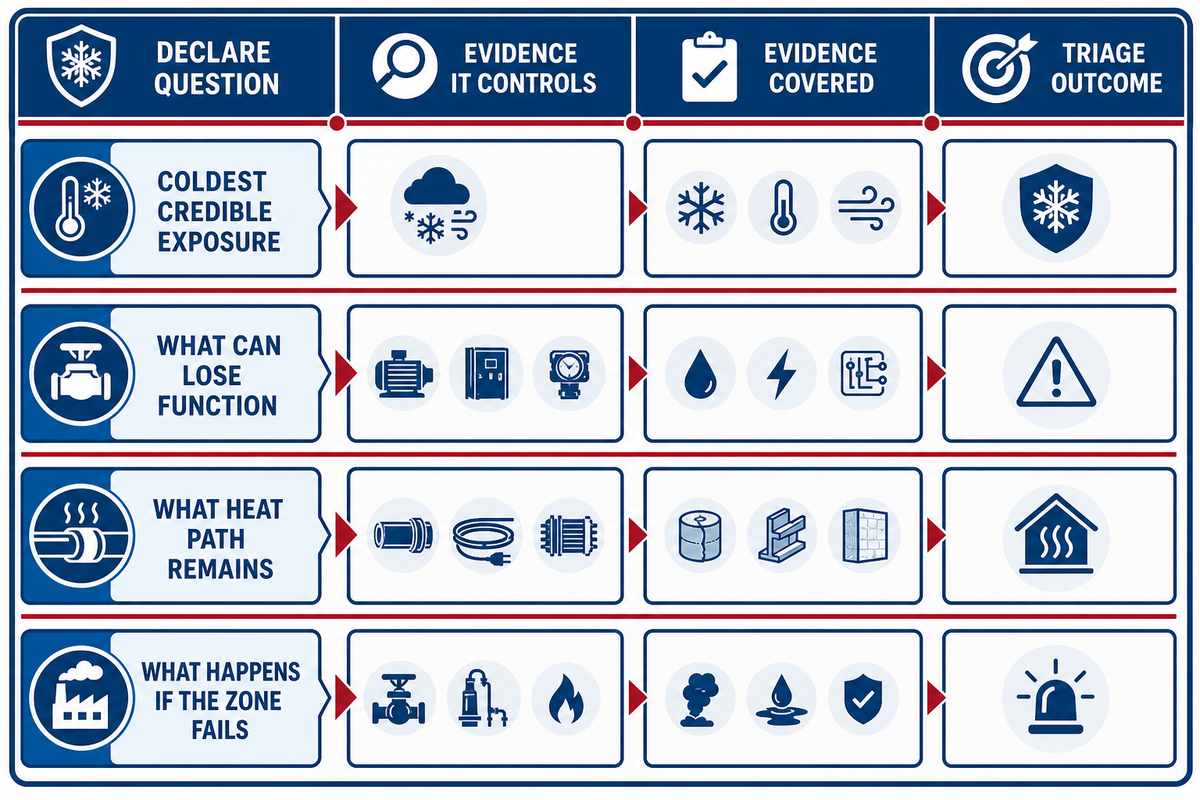
Industrial freeze exposure is defined by actual air temperature, wind-driven cooling, material limits, residual heat, flow state, and failure consequence. A cable trace or fitted blanket route only becomes defensible after the exposure case is recorded. Human wind chill isn’t an equipment temperature. Wind can shorten the cooling time of an exposed pipe, but it can’t make that pipe colder than actual outdoor air temperature.
National Weather Service wind-chill guidance makes that distinction explicit. Wind still belongs in a heat-loss model because it changes convective heat transfer; the wind-chill number shown for people doesn’t replace measured or design air temperature for equipment.
4-Question Freeze Exposure Triage
The 4-Question Freeze Exposure Triage is a pre-hardware screening tool, not a standard or numerical risk score.
- What is the coldest credible exposure? Record actual air temperature, wind, washdown, radiation to the sky, enclosure condition, burial depth, and event duration.
- What can lose function? Identify free water, aqueous phases, process fluid, condensate, hydrate risk, instruments, vents, seals, and moving parts.
- What heat path remains? Document flow, stored heat, building heat, insulation, circulation, active heat, backup power, and what disappears during shutdown.
- What happens if the zone fails? Rank lost supply, blocked relief or venting, pressure damage, delayed leakage, environmental release, life-safety impairment, and production loss.
U.S. Chemical Safety Board winterization guidance adds an important boundary: ice damage may remain hidden until temperatures rise and the ice thaws. That turns post-event inspection into part of freeze protection, not an optional cleanup step.
Engineering note
Buried and partially buried assets need a separate frost-depth, soil, foundation, piping-flexibility, and thaw-instability review. Surface insulation or an electric heater doesn’t resolve geotechnical frost-heave loads.
Why Pipes and Tanks Fail Differently in a Freeze
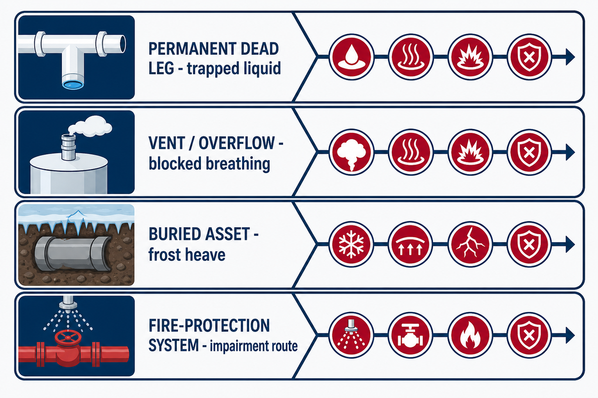
Pipes, dead legs, valves, instruments, tanks, outlets, vents, and buried supports don’t share one freeze mechanism. The preceding buried-asset example shows why frost-heave and other failure mechanisms must be separated by zone. Some zones lose flow; others crack from expansion, collapse under vacuum, shift under frost heave, or become an impaired life-safety system. Inspection and escalation must follow the actual failure mode.
An AIChE process-safety case history documents water trapped in a dead leg freezing and cracking a 10-inch propane line. That diameter is 254 mm. The lesson isn’t that every dead leg fails; it’s that low-flow and out-of-service configurations belong in the asset inventory.
The Chemical Safety Board also warns that thawing can expose damage that was sealed by ice. A cold-event closeout therefore needs leak checks, instrument review, and exception closure after temperatures recover.
Pipe-or-Tank Freeze Consequence Board
The Pipe-or-Tank Freeze Consequence Board assigns 12 asset zones to an evidence check and accountable role before a forecast event.
| Zone | Primary freeze path | Evidence before release | Accountable role | Limitations / Not suitable for |
|---|---|---|---|---|
| 1. Straight pipe | Heat loss exceeds retained or supplied heat | Geometry, actual ambient, wind, insulation, flow | Process / mechanical | No universal W/m or W/ft |
| 2. Permanent dead leg | Stagnant retained liquid freezes and expands | P&ID, walkdown, positive-isolation record | Operations / integrity | Drawing alone may miss field condition |
| 3. Temporary dead leg | Valve position or shutdown removes normal flow | Operating-state review and shift plan | Operations | Cannot be identified from normal-state flow only |
| 4. Valve or flange | Local heat sink, cavity, poor coverage | Surface geometry, contact, service access | Maintenance / mechanical | Straight-pipe assumptions do not transfer |
| 5. Instrument line | Small stagnant volume loses process heat | Impulse route, body, manifold, sensing point | Instrumentation | Parent pipe temperature is not proof |
| 6. Pump casing | Trapped liquid or idle service | Drainability, standby state, restart procedure | Operations / rotating equipment | Do not energize against unresolved trapped fluid |
| 7. Tank wall | Area heat loss and nonuniform internal convection | Area, construction, contents, fill, insulation | Process / vessel engineer | One wall point does not equal bulk temperature |
| 8. Tank outlet | Small passage, stagnant pocket, exposed valve | Outlet geometry, draw pattern, cold-point survey | Operations / process | Bulk tank temperature is not sufficient evidence |
| 9. Drum or IBC | Material loses flow or aqueous phase freezes | Container rating, contents, fill, Safety Data Sheet | Environmental health and safety / procurement | Heater-sheath limit is not material temperature |
| 10. Vent / overflow | Snow or ice blocks tank breathing | Vent inspection and withdrawal scenario | Tank owner / integrity | Acceptable liquid temperature does not prevent vacuum collapse |
| 11. Buried asset | Frost heave and thaw instability load structure | Frost depth, soil, foundation, ancillary piping | Civil / geotechnical | Surface heating is not a structural design |
| 12. Fire-protection system | Frozen or damaged water-based protection becomes impaired | Site impairment notice, adopted code, inspection and test route | Fire protection / authority | Do not use the ordinary process-pipe procedure |
The U.S. Environmental Protection Agency tank alert confirms the vent row: snow or ice can restrict a vent, and liquid withdrawal can pull a vacuum that collapses a tank inward.
Define the Freeze-Protection Duty Before Choosing Hardware
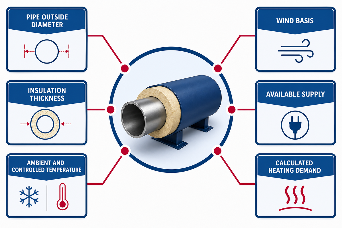
Freeze-protection duty is the heat required to keep the controlled zone above its project limit under the coldest credible operating case. Once the vent and vacuum collapse path is separated, thermal duty can be assigned to a controlled zone instead of a generic asset. Calculation starts with geometry, thermal conductivity, insulation, actual air temperature, wind, surface area, flow state, and event duration; it doesn’t start with a catalogue wattage.
Oak Ridge National Laboratory cylindrical-resistance documentation shows why diameter and conductivity matter for a pipe or insulation annulus. Its wall heat-loss documentation separately includes surface area, temperature difference, geometry, operating condition, and wind.
A useful input sheet also states the duty: prevent water from freezing, keep a process fluid pumpable, protect an instrument line, or warm material over a defined period. Pure water’s familiar 32°F (0°C) phase reference is not a universal process-fluid limit; contents and current material data still govern. Freeze protection and controlled warm-up aren’t interchangeable promises.
Worked input-completeness example
Brief A says: “2-inch (50.8 mm) pipe, keep above freezing.” Brief B records the same nominal size plus material, outside diameter, straight length, four exposed valves, insulation type and thickness, minimum actual air temperature, wind basis, stagnant-outage duration, available voltage, and acceptance test.
For example, a calculation record could contain fields such as 50 mm outside diameter, 9 m exposed length, 50 mm insulation, −23°C design ambient, 4°C minimum controlled temperature, and 480 V supply. Those values only illustrate a complete record format; they aren’t a design recommendation and must not be copied into another project.
Brief B can support a calculation and responsibility review. Brief A can’t. No wattage is calculated here because unverified project inputs would create false precision.
25-Field Freeze-Protection Data Format Register
The values below show how units can be recorded in one comparable request. They are formatting examples only, not setpoints, heater ratings, code limits, or FlexBlanket product specifications; replace every value with verified project data.
| Record field | Example formatting only | Project evidence that replaces the example |
|---|---|---|
| Pipe outside diameter | 50 mm / 100 mm | Field measurement and drawing |
| Exposed length | 2 m / 5 m | Walkdown including fittings and dead legs |
| Insulation thickness | 25 mm / 50 mm | Installed system and condition record |
| Ambient and controlled temperature | −20°C / 4°C | Design weather and process limit |
| Wind basis | 20 mph / 10 m/s | Site exposure model, not human wind chill |
| Available supply | 120 V / 240 V / 480 V | Approved panel and circuit record |
| Circuit current | 15 A / 30 A | Calculated load and protection design |
| Calculated heating demand | 1 kW / 2 kW | Project heat-loss or warm-up calculation |
| Cold-event duration | 24 hours / 72 hours | Forecast and operating scenario |
| Test sampling interval | 5 min / 10 min | Commissioning and trend plan |
| Pressure condition | 10 psi / 1 bar | Process and isolation procedure |
| Supply frequency | 50 Hz / 60 Hz | Site electrical standard |
Use the site’s duty and design temperature difference worksheet to note the thermal goal prior to hardware comparison.
When Insulation Is Not Enough for Exposed Pipes
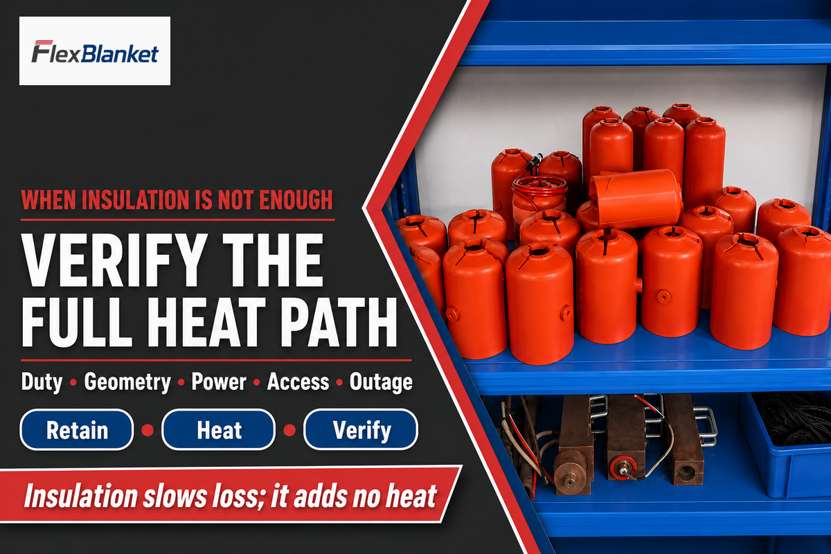
Insulation suffices only when the entire heat path maintains the pipe above its required minimum for the entire exposure duration. The preceding thermal duty and design-temperature record now become inputs to the full heat-path review. It slows heat loss but creates no heat. Long cold events, stagnant service, damaged jackets, wind, valves, supports, instruments, or a power-loss case may call for an engineered active or non-electric solution.
Current IEEE/IEC 62395-2-2024 application guidance treats design, installation, maintenance, and repair as one lifecycle for ordinary industrial resistance trace and assembled surface-heating systems. Its scope excludes potentially explosive atmospheres, so it cannot be used to imply hazardous-area suitability.
What can I put on my pipes to keep them from freezing?
Industrial classes include weather shielding, insulation, controlled electric heat, steam or fluid tracing, circulation, drainage, enclosure heat, and purpose-built freeze-defense accessories. Selection depends on the duty, geometry, process, classification, power, access, and outage case. A product name alone can’t answer those questions.
Use the site’s pipe-geometry heating family as one product reference for serviceable pipe layouts. The direct cable-versus-blanket comparison is reserved for the separate site article and isn’t included here.
A supplier-authored Plant Engineering article argues that insulation may be insufficient in extreme weather. It was written by Christine Tarlecki in a ThermOmegaTech marketing role, so it is used only for industry problem framing; its product claims are excluded.
Tank Freeze Protection Starts With the Material and Outlet
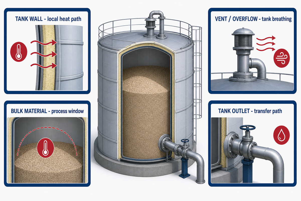
Freeze protection of a tank begins with identification of the item to be controlled: wall, bulk material, outlet, valve, transfer line, instrument, vent, or support structure. When insulation is not enough, the same heat-path test extends to a tank only after wall, bulk, outlet, and vent zones have been separated. Each zone has a different heat path and failure result. A warm wall does not establish a free outlet, a breathing vent, or a consistent bulk temperature.
An industry-cofunded dynamic tank temperature-profile pilot study, whose funding disclosure includes Petrobras S.A. and public institutions, observed different temperatures at different sensor positions as convection changed during heating and cooling. The study is evidence of the mechanism, not a recommended industrial sensor layout.
Tank breathing is a separate safety path. EPA guidance warns that snow or ice can block vents and that withdrawal through a restricted vent can create inward-collapse vacuum. Vent inspection therefore belongs beside temperature checks.
Do
- Confirm the current container or vessel specification
- Review the contents and current Safety Data Sheet
- Map wall, outlet, valve, vent, and instrument zones
- Define whether the duty is freeze protection or controlled warm-up
Don’t
- Treat heater-sheath temperature as material temperature
- Assume one wall sensor represents the bulk liquid
- Ignore vent blockage because the liquid remains warm
- Apply aboveground heating logic to buried structural loads
Buried and partly buried tanks need a separate frost-heave and thaw-instability review. Older EPA tank-system guidance identifies frost depth and shallower ancillary piping as structural variables; current local codes and a qualified engineer must govern the actual design.
For product-family routing, review the site’s container heating options that include tanks and totes.
Place Sensors at the Coldest Credible Point
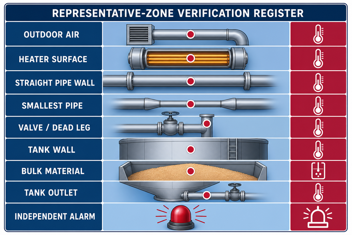
A controller reacts only to the temperature its sensor measures. Those tank and container zones become the measurement map for control and verification. Using the coldest expected location is a starting assumption, not evidence that one point monitors every branch, valve, dead leg, or instrument. Representative-area planning isolates heater, pipe wall, tank wall, material, outlet, instrument, and ambient readings and indicates which decision each point influences.
The ASHRAE freeze-protection handbook says pipe sensing is complex because a reading must represent all pipe areas; it advises the smallest pipe and coldest anticipated location. That doesn’t turn one sensor into proof for every branch, valve, dead leg, or instrument.
Another peer-reviewed vessel study mapped wall temperature at multiple positions and showed that wall conduction and free convection influence nearby readings. This is evidence of measurement uncertainty, not a universal point count.
9-Point Representative Zone Verification Register
| Point | Object | Question the reading answers | Verification evidence | Limitations / Not suitable for |
|---|---|---|---|---|
| 1 | Outdoor air | What exposure drives the loss model? | Actual temperature and wind basis | Do not substitute human wind chill |
| 2 | Heater surface | Is the heater within its own limit? | Manufacturer instruction and over-temperature protection | Does not prove pipe or material temperature |
| 3 | Straight pipe wall | Is the controlled run above its limit? | Contact, insulation, functional test | Does not cover branch or valve |
| 4 | Smallest pipe | Does the low-thermal-mass zone cool first? | Zone map and alarm response | Not automatically the most critical consequence |
| 5 | Valve / dead leg | Is stagnant material protected? | Walkdown under the actual operating state | Normal-flow drawing may be misleading |
| 6 | Tank wall | What is the local wall heat path? | Multiple points or validated model | Wall is not bulk material |
| 7 | Bulk material | Is the material within its process window? | Approved internal measurement or sample method | May lag or stratify relative to wall |
| 8 | Tank outlet | Can the transfer path function? | Outlet-zone reading and flow confirmation | Warm bulk does not prove a free outlet |
| 9 | Independent alarm | Will loss of control or power be detected? | Alarm test, notification path, exception record | Alarm does not supply heat or restore power |
Use the site’s freeze-protection design record check to capture the controlled object, location, test result, exception, and owner.
Plan for Power Loss Before the Cold Front
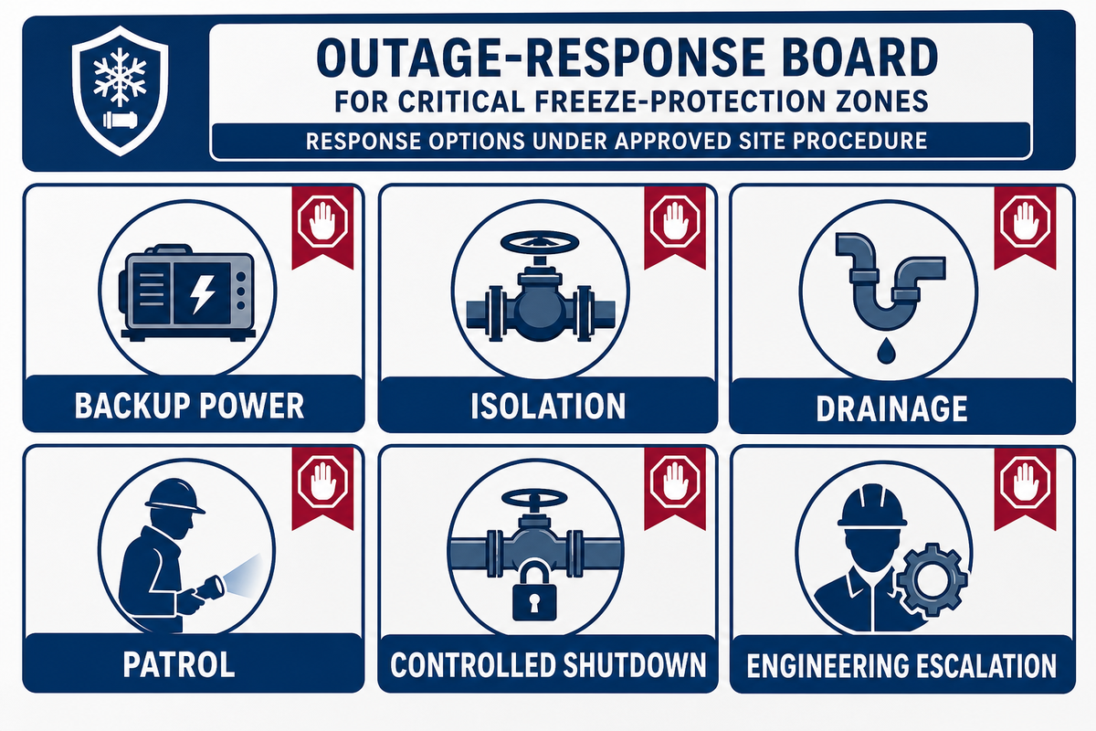
An electrical freeze-protection system needs a defined outage case. For every critical zone, decide what happens when heater power, circulation, building heat, communications, or staffing is lost. Approved responses can include backup power, isolation, drainage, patrol, alternate heat, controlled shutdown, or engineering escalation.
The Chemical Safety Board’s December 9, 2024 winterization release calls for equipment-specific written plans, assigned responsibility, documented implementation, and periodic audit. That’s a stronger operating model than “turn the heater on when it gets cold.”
“Every chemical facility must take steps now to winterize its processes.”
How do I keep my pipes from freezing if I lose power?
An industrial facility first protects people and process containment, then follows its approved isolation, drainage, backup-power, patrol, or shutdown procedure. Preserve low-temperature monitoring where possible, identify zones that become stagnant, and escalate chemical, pressure-boundary, buried, inaccessible, or hazardous-area decisions before applying alternate heat.
Questions about how to keep pipes from freezing, whether to insulate exposed pipes, and when do pipes freeze are only the starting point in an industrial setting. How to prevent frozen pipes from bursting, how to keep pipes from freezing without power, and the minimum temperature to keep pipes from freezing all depend on process contents, geometry, operating state, pressure boundary, discharge route, and approved response. A water pipe, water supply, or instrument run near an exterior wall still needs that evidence; industrial fluids and pressure boundaries don’t simply freeze and burst in one uniform way. Household advice may mention dripping a faucet, using a hair dryer, or calling a plumber; it doesn’t become a plant instruction. Even the American Red Cross residential guide warns against blowtorches, kerosene or propane heaters, and other open flame devices. Industrial actions need the site’s process, electrical, fire, environmental, and area-classification review.
Residential Phrase-to-Industrial Decision Map
General cold-weather guidance uses household shorthand that can be unsafe or incomplete at a plant. The map preserves that familiar language for recognition, then assigns the industrial evidence or authority needed before anyone acts.
| Household phrase family | Phrases a team may encounter | Industrial decision boundary |
|---|---|---|
| Generic prevention | “protect your pipes”; “help prevent frozen pipes”; “prevent pipes from freezing”; “avoid frozen pipes”; “prevent your pipes from freezing”; “prevent them from freezing”; “helps prevent pipes from freezing”; “keep your pipes from freezing”; “keep your pipes”; “prep your pipes” | Replace the generic pipe with a zone list, material limit, exposure case, duty, owner, and acceptance record. |
| Burst consequences | “pipes from freezing and bursting”; “burst pipe”; “cause pipes to break”; “pipes have burst”; “cause pipes”; “expanding water can cause pipes”; “additional frozen pipes”; “pipes to freeze” | Treat blockage, cracking, pressure release, delayed thaw leakage, and adjacent-zone exposure as separate consequences. |
| Flow and dripping | “running water”; “running water through the pipe”; “water running”; “water drip”; “let the cold water drip”; “water drip from the faucet” | Use only an approved flow and discharge procedure that addresses pressure, contents, environmental duty, and dead legs. |
| Isolation | “turn off the water”; “main water valve”; “water at the main shutoff”; “water shutoff valve” | Follow the site’s energy-control, isolation, depressurization, drainage, and restart authority. |
| Drain and supply | “drain water”; “standing water”; “water system”; “water supply lines”; “hot and cold water pipes”; “water service enters your home” | Map trapped process material, instrument lines, fire water, utilities, drains, low points, and continuity obligations separately. |
| Finding a blockage | “frozen section”; “locate the frozen area”; “locate the frozen”; “frozen area is not accessible” | Control pressure and energy first, then use the site’s approved inspection, isolation, thawing, and escalation route. |
| Applying heat | “leave the heat”; “help melt”; “heat tape”; “keep the thermostat set”; “heat on in your home” | Verify material, vessel, electrical, area-classification, fire, control, and over-temperature limits before adding heat. |
| Weather threshold | “away during cold weather”; “risk of freezing”; “susceptible to freezing”; “freezing weather”; “exposed to severe cold”; “temperature no lower than 55°” (55°F / 13°C household advice) | Use actual design weather, wind, duration, operating state, residual heat, material limit, and response time instead of a household threshold. |
| Role and safety | “call a licensed plumber”; “away from flammable materials”; “water damage”; “water sprinkler lines” | Assign the qualified plant role and keep hazardous materials, containment, and fire-protection impairment on their separate authority routes. |
Hold the Job at the Safety and Approval Gate
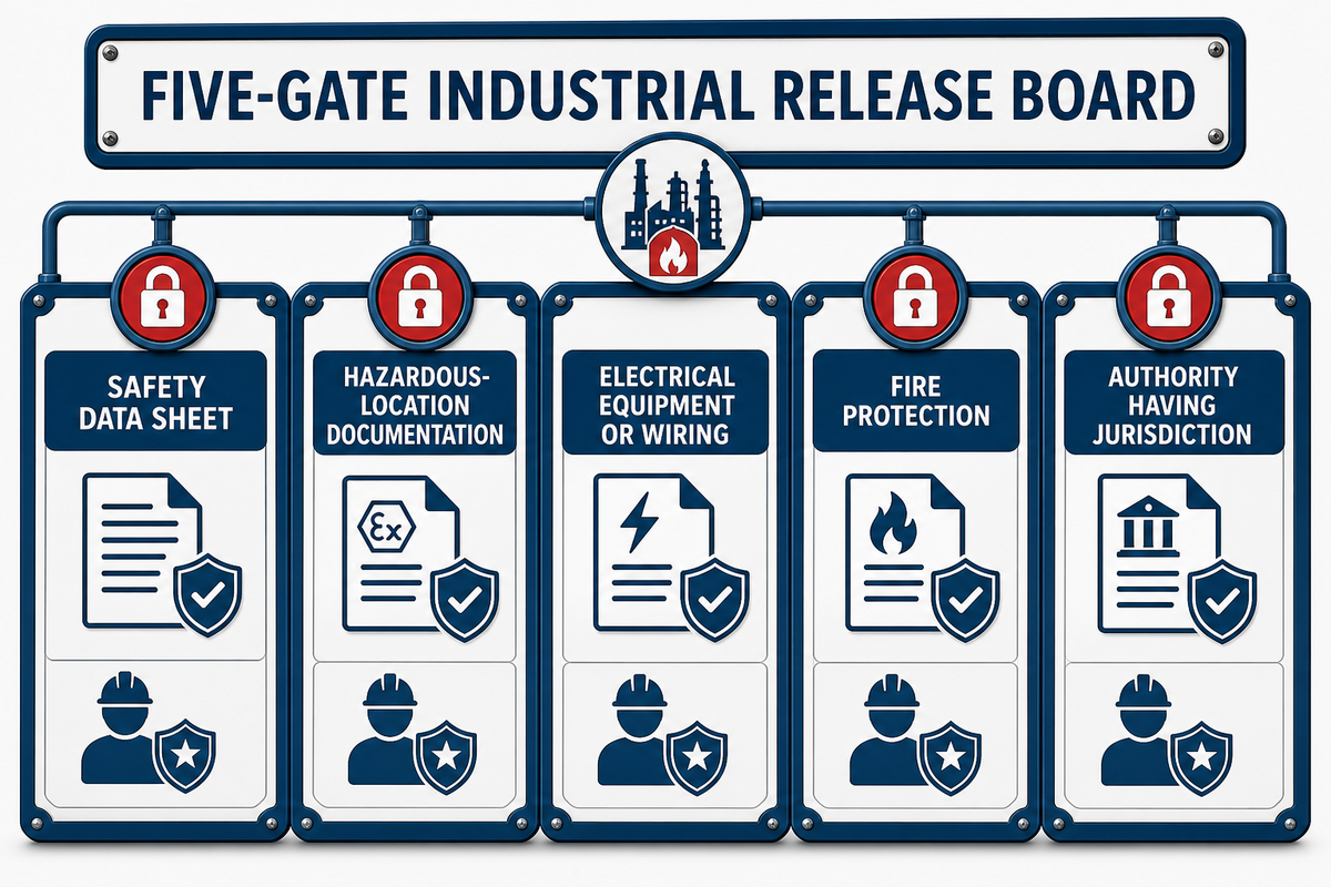
Freeze-protection work stays on hold when material behavior, vessel limits, hazardous-area classification, electrical approval, fire-protection impairment, or installation responsibility is unresolved. That household-language evidence map still stops at the plant’s safety authority. An ingress rating, heater temperature limit, or catalogue description can’t answer all of those questions. Each gate needs its own evidence and accountable reviewer.
This guide uses U.S. OSHA and NFPA materials as a United States baseline; projects in other markets must follow their local electrical, hazardous-area, fire-protection, and authority requirements.
For a heated chemical, OSHA Safety Data Sheet Appendix D separates Section 7 handling and storage, Section 9 physical and chemical properties, including melting or freezing point and flammability, and Section 10 stability and reactivity. Read all three; a freezing point alone isn’t a heat-suitability decision.
OSHA 1910.307 separately requires hazardous-location documentation and electrical equipment or wiring suitable for the actual gas, vapor, dust, or fiber and its likelihood of presence. Nearby flammable materials and classified atmospheres require different evidence; an enclosure’s water-ingress rating isn’t hazardous-location approval.
Water-based fire protection is also a separate route. Official NFPA 25 committee material on frozen systems treats discovery as an impairment case and discusses thawing, damage inspection, testing, and restoration. Control belongs to the adopted edition, site impairment procedure, and authority having jurisdiction, not this article.
Release rule
Don’t energize a heater because the weather is urgent. Resolve material, vessel, area, electrical, fire-system, installation, and acceptance evidence first.
Run the 72-Hour Cold-Front Readiness Loop
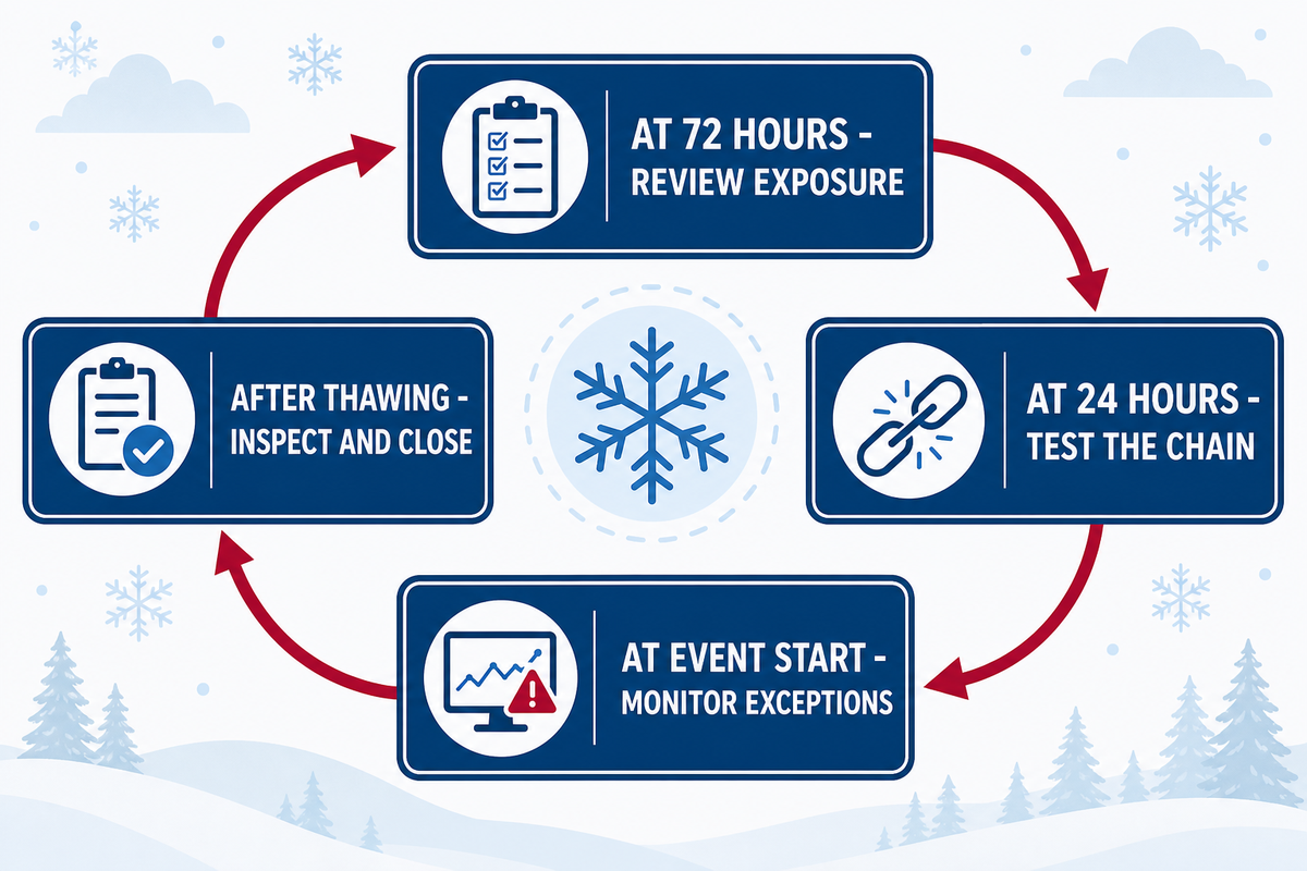
Cold-front readiness is a closed evidence loop: review exposure and ownership at 72 hours, function-test the protection chain at 24 hours, monitor the coldest representative zones when the event starts, then inspect after thawing and close every exception. Once electrical and fire-system approval holds are resolved, the same zones, alarms, and owners move into the event-readiness loop. This timing is an editorial planning frame; the site’s forecast and procedures set actual deadlines.
- At 72 hours, review the exposure list — confirm the forecast basis, operating state, temporary dead legs, vulnerable vents, buried boundaries, backup power, and accountable owner.
- At 24 hours, test the complete chain — inspect insulation and jackets; function-test circuits, controllers, representative sensors, alarms, notifications, and documented backup routes.
- At event start, monitor exceptions — trend actual air and zone temperatures, record power or flow loss, patrol high-consequence zones, and open an exception before the limit is reached.
- After thawing, inspect and close — check leaks, cracks, instruments, vents, supports, and impaired systems; retest affected zones and retain the evidence for the next review.
CSB program elements provide the spine: identify vulnerable equipment, select options, establish written plans, assign responsibility, document implementation, audit the program, and review out-of-service piping. The 72-Hour Cold-Front Readiness Loop turns those elements into a repeatable event workflow without claiming that one schedule fits every plant.
Post-event point
A zone that remained above its alarm threshold can still require inspection when vents, supports, fire protection, or adjacent stagnant sections were exposed to a different failure path.
Send a Complete Pipe or Tank Freeze-Protection Brief
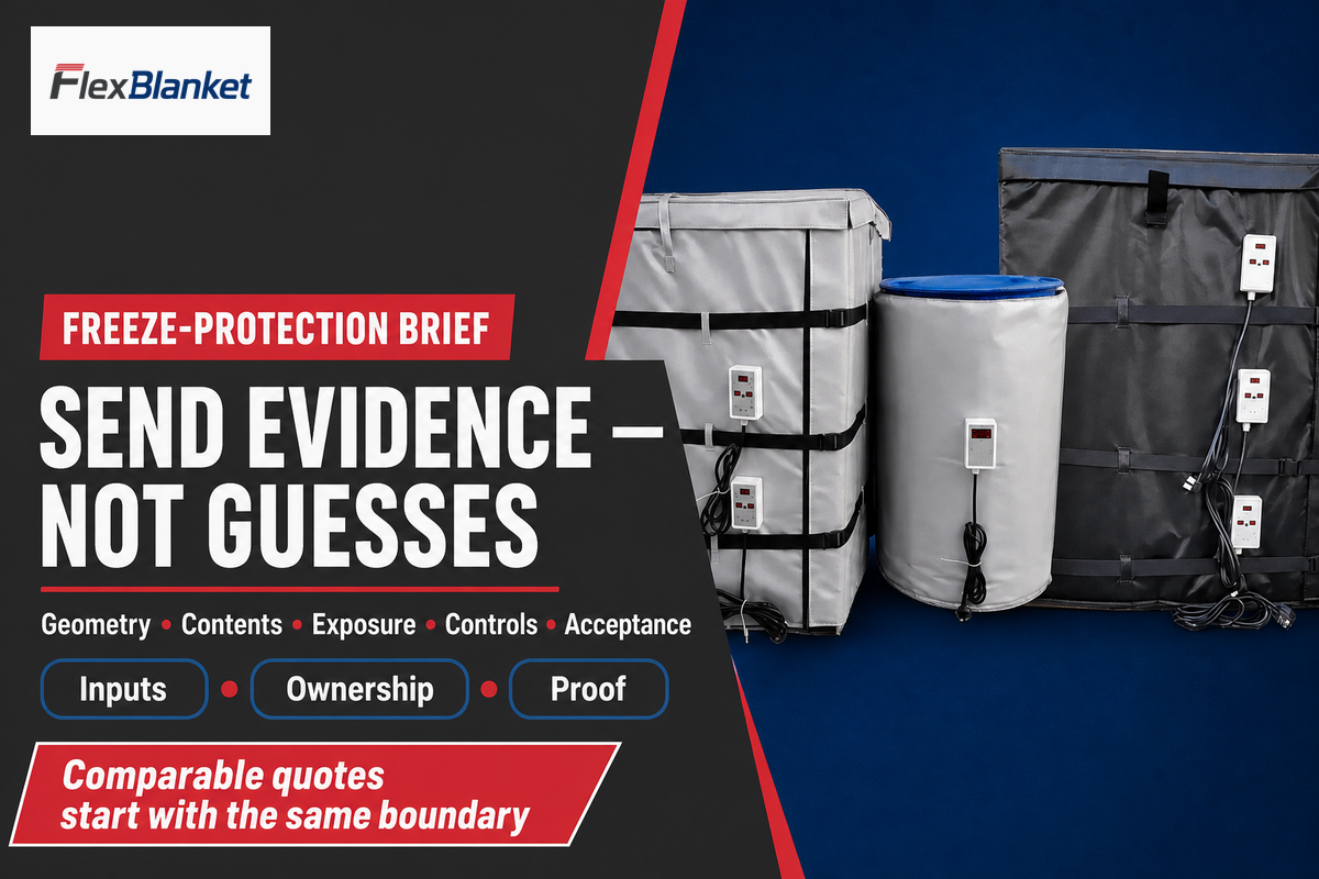
A comparable freeze-protection proposal starts with the same asset list, geometry, contents, temperatures, exposure, insulation, classification, power, sensing, outage, responsibility, and acceptance evidence. That zone inspection and failure-path record supplies the evidence set that a supplier needs before quoting. A shorter quote may appear cheaper because design, field work, controls, testing, documentation, or future access has been omitted rather than because the solution costs less.
Copy the following fields into the request. Record temperature in °F or °C, pipe outside diameter and insulation thickness in inches or millimetres (in or mm), exposed length in ft or m, wind in mph or m/s, and electrical demand in W only after calculation. Where an item is unresolved, mark it as an engineering hold instead of inviting the supplier to guess.
| Input family | Record | Why it matters | How to verify |
|---|---|---|---|
| Asset and geometry | Pipe/tank material, dimensions, fittings, outlets, vents, dead legs, burial | Defines heat and structural paths | Drawing plus field walkdown |
| Thermal duty | Contents, start/minimum/target temperatures, ambient, wind, duration, flow | Separates freeze protection from warm-up | Calculation basis and assumptions |
| Safety and approvals | Safety Data Sheet, vessel limit, area classification, fire-system status | Prevents category and approval errors | Current documents and authorized reviewer |
| Controls and acceptance | Supply, zones, sensors, alarms, outage, installation, tests, records | Defines the complete installed system | Functional test and signed exception closure |
For the user-supplied commercial destination, review the duty-and-method solution hub. FlexBlanket can use a complete brief to discuss a project-specific route; this article makes no promise about wattage, certification, price, lead time, or performance.
Key takeaway
Freeze protection is complete only when every vulnerable zone has a verified duty, heat path, representative sensor, outage response, and accountable owner.
Turn the exposure list into an engineering brief
Send FlexBlanket the asset geometry, contents, exposure, insulation, power, controls, and acceptance requirements. Unresolved safety or approval items remain hold points.
Request a Freeze-Protection Review →send your pipe or tank freeze-protection brief
FAQs: Prevent Frozen Pipes and Tanks
What temperature should trigger an industrial freeze-protection plan?
No single outdoor temperature can replace the site’s design-weather and heat-loss review; use actual air temperature, wind, material limits, geometry, operating state, and response time.
Trigger selection depends on the material, pipe or vessel geometry, insulation condition, actual air temperature, wind, exposure time, flow state, residual heat, and required minimum temperature. Establish the design case, then set alarms with enough time for the approved response. Check dead legs, outlets, vents, instruments, power loss, and shutdown states separately because they may cool or fail differently from the main asset. Human wind chill describes heat loss from exposed skin; it is not an equipment temperature or a substitute for measured air temperature.
Can insulation alone prevent an industrial pipe from freezing?
Insulation can prevent freezing only when verified retained heat and operating conditions keep every vulnerable pipe zone above its required minimum for the full exposure period.
Insulation slows heat transfer but supplies no heat. Verify its thickness, conductivity, condition, weather jacket, wind exposure, flow state, event duration, valves, supports, instruments, and outage case. Exposed, stagnant, critical, or long-duration cases may require controlled active heat, circulation, drainage, enclosure heat, or another engineered measure. Recheck the result whenever process flow, insulation condition, or minimum design weather changes.
Can one sensor protect a tank and its outlet?
One sensor can protect both zones only when a validated design proves its reading represents the tank wall, bulk material, outlet, valve, vent, and transfer path.
Tank wall, bulk material, outlet, valve, transfer line, vent, instrument, and heater can sit at different temperatures. Define the controlled object and representative zones, then decide whether separate sensors, alarms, or protection are required. Verification records should connect each reading to an alarm, control action, or inspection decision. A wall reading does not automatically prove bulk or outlet temperature.
Should an industrial facility drip water to keep pipes from freezing?
Do not adopt a household dripping-faucet recommendation as an industrial procedure; flow can be unsafe, prohibited, unavailable, or unable to protect dead legs and instruments.
Not by default. Flow can be unsafe, prohibited, unavailable, or unable to protect dead legs. Follow the approved process and discharge procedure.
What should a plant do if a pipe is already frozen?
Treat a frozen industrial pipe as an abnormal operating and containment condition: control pressure and energy, protect people, isolate the system, and follow the approved thaw procedure.
Identify the system, control pressure and energy sources, protect people and nearby equipment, and follow the site’s isolation and thawing procedure. Do not use open flame or an unreviewed portable heater. Escalate hazardous, chemical, pressure-boundary, buried, fire-protection, or inaccessible sections before applying heat.
What should a freeze-protection quotation include?
A comparable quotation must state the thermal, mechanical, electrical, control, installation, inspection, acceptance, outage, documentation, and responsibility boundary for the same defined asset zones and scope.
Provide drawings, geometry, contents, operating and minimum temperatures, actual design ambient, wind, insulation, classification, supply, zones, sensors, alarms, outage duration, access, installation responsibility, inspection, and acceptance evidence. Require every supplier to state assumptions, exclusions, field work, documents, tests, spares, and responsibility for the final calculation. Ask who verifies field dimensions, performs the heat-loss calculation, selects over-temperature protection, approves hazardous-location equipment, installs the system, tests alarms, closes exceptions, and retains the commissioning record. Quotes are comparable only when they price the same boundary.
How This Freeze-Protection Guide Was Built
The guide combines current government, standards-body, peer-reviewed, buyer-question, and industry evidence. No private plant measurements, FlexBlanket field results, customer performance data, or universal product values were supplied; every decision asset therefore uses buyer-entered evidence, named responsibility, and explicit limits throughout.
Related Articles
References & Sources
- Wind Chill Questions National Weather Service
- Winterization U.S. Chemical Safety and Hazard Investigation Board
- Valero McKee Refinery Propane Release and Fire American Institute of Chemical Engineers
- Rupture Hazard from Liquid Storage Tanks U.S. Environmental Protection Agency
- Protection Against Frost Heave U.S. Environmental Protection Agency
- Insulated Pipe Thermal Resistance Formula Oak Ridge National Laboratory
- IEEE/IEC 62395-2-2024 IEEE Standards Association
- Dynamic Temperature Profile Monitoring in a Tank Peer-reviewed research in PubMed Central
- Snow Melting and Freeze Protection, Chapter 51 ASHRAE Handbook
- Chemical Facilities and Extreme Cold Weather U.S. Chemical Safety Board
- Preventing and Thawing Frozen Pipes American Red Cross, residential boundary only
- Safety Data Sheets, Appendix D Occupational Safety and Health Administration
- Hazardous Classified Locations, 1910.307 Occupational Safety and Health Administration
- NFPA 25 Committee Material on Frozen Systems National Fire Protection Association, edition and authority limits apply