Get in touch with FlexBlanket Company

Heat trace supplies heat to a pipe to replace heat lost to the surrounding environment. Electric systems make use of heating cable and suitable connections and controls. The choice depends on the duty, pipe material, insulation and cold-start conditions and not the length of the cable alone.
A pipe can freeze while its power indicator is on. It can also overheat beneath the wrong covering. The complete system should be designed to accommodate the line, including the valve, the outdoor support and the section that maintenance personnel must open. This guide covers electric pipe heat tracing. Steam and hot-fluid tracing aren’t covered.
What Is Heat Trace and How Does It Work?
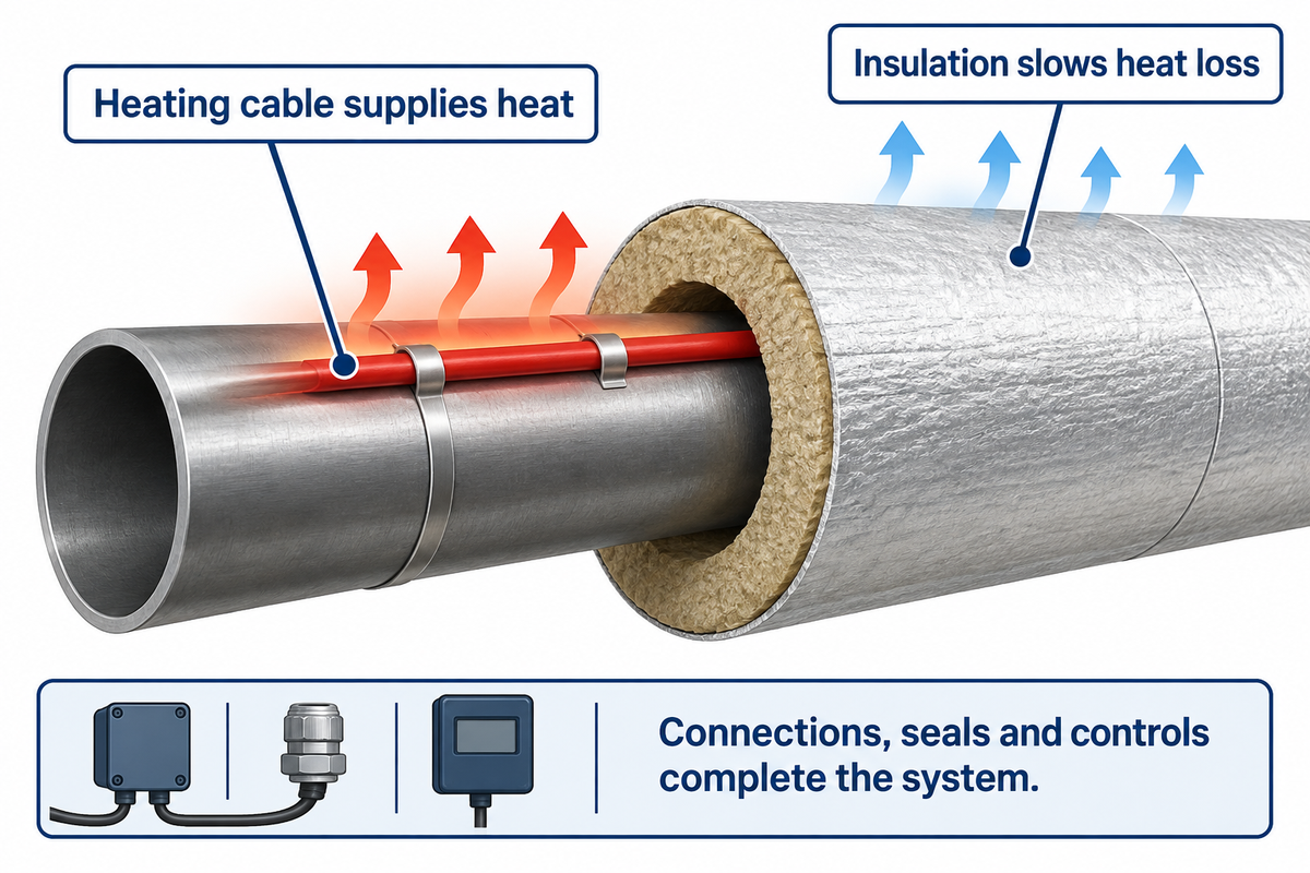
Electric heat trace converts electrical energy into heat along a heating element which is attached to a pipe. The heat replaces the losses in the pipe insulation and surrounding air. A working heating system also needs compatible power connections and end seals and controls; the cable alone doesn’t determine the pipe temperature.
Thermon’s industrial installation manual illustrates a complete system with connections, insulation and temperature control equipment. It shows a suitable arrangement for industry; however, consumer heat tape has covering restrictions. The product instructions determine whether insulation may cover it. A pipe heater isn’t automatically suitable for roof and gutter heat applications or gutter de-icing.
Consider insulation as slowing heat escape rather than as generating heat. In a prolonged cold spell, an unheated line can still approach ambient temperature. Given this, adding an additional layer of covering can’t replace a heat loss assessment. For plumbing systems, this distinction is covered in the ASPE discussion of heat tracing and heat trapping.
Pipe Freeze Protection or Process Temperature Maintenance?
Pipe freeze protection keeps a vulnerable line above its freezing condition. Process temperature maintenance holds a fluid within a specified operating range which can be quite a bit warmer. State the duty first, then decide whether to use cable: maintaining temperature, warming a cold process and recovering frozen pipes are different design problems with different heat requirements.
For an exposed building line, the ASPE freeze-protection discussion illustrates why pipe size, flow and winter exposure belong in the design brief.
Consider a hypothetical packaging plant with an outdoor water branch used only during cleaning. The production occurs indoors and the water line is left outdoors, with water in it, during off hours. A buyer using the plant’s normal indoor temperature as the design basis would overlook the exposed section and its valve. The design brief should specify the lowest expected outdoor conditions, idle time, pipe size and insulation, and ask the supplier to assess the entire route. The maintenance personnel should also have access to the valve after the heater is installed. If the water line is holding a product that has to remain warm enough to flow, the fluid temperature requirement is a different input. The same physical route doesn’t mean the same design requirement.
The 3-Check Heat Trace Fit Test
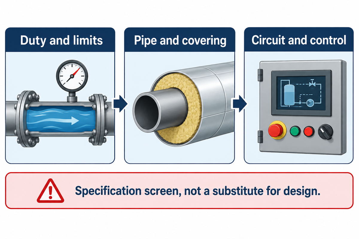
Use these three decisions in order. If any of these decisions is missing, send back the specification for clarification; this isn’t authorization to select a higher wattage.
- Duty and limits: If the goal is freeze prevention, specify the fluid and minimum design conditions. For process maintenance, give the operating temperature range and maximum allowable temperature during cleaning and shutdown.
- Pipe and covering: If the insulation condition or material compatibility is unknown, determine this before making a selection. If valve access is required, assess its heating arrangement separately.
- Circuit and control: If the proposed design exceeds the limits of the product for cold-start or length, revise the design for a different circuit arrangement. It isn’t appropriate to designate a larger protective device as the solution.
This is a specification screen, and not a substitute for the supplier’s design. Consistent heat at the required locations is more critical than an energized indicator. A system designed to prevent freezing shouldn’t be presumed to be capable of thawing a frozen line.
Self-Regulating Heat Trace and Constant-Wattage Cable
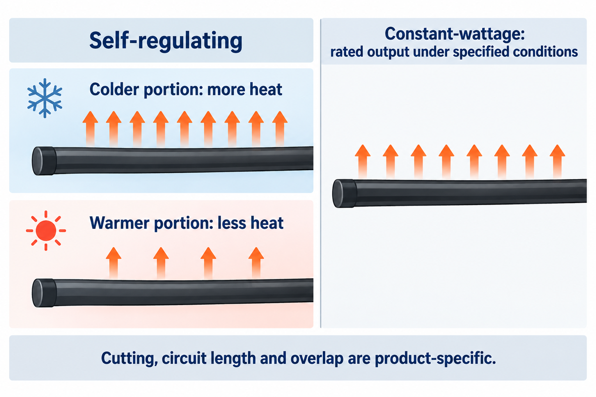
Self-regulating tracing cables adjust local heat output through changes in conductive polymer resistance with temperature. Constant-wattage heating uses a different electrical arrangement to provide its rated output under specified conditions. Allowable temperature, cutting rules, circuit length and permission for two portions to cross are product-specific.
Self-regulating heat responds to temperature changes along a route: colder portions within product operating range produce more heat than warmer portions. That response doesn’t mean zero consumption when warm, nor does it guarantee precise temperature control. Circuit construction for constant-wattage products is different; series heaters and parallel zonal heaters must not share assumed cutting instructions.
Can heat trace touch itself?
This is permitted only when the exact product instructions allow it. Thermon’s BSX self-regulating cable documentation allows overlap, while its installation manual prohibits heating portions of named HTEK, TEK and TESH series heaters from touching, crossing or overlapping. These are product-specific rules, not permission for every self-regulating cable product to overlap or a single rule for every constant-wattage product.
For consumer products, CPSC heat-tape guidance likewise makes wrapping tape over itself conditional on specific permission in the manufacturer’s instructions.
While reviewing the model printed on the cable and the existing instructions on installation, determine how the surplus length should be routed. Other limiting factors may include the exposure temperature, insulation and the manner in which the circuit is constructed. “It can self-regulate” doesn’t allow the approval of a tight loop or an improvised splice. Ask for a marked routing drawing when the shape makes the installation unclear.
Heat Trace Sizing for Pipe Material and Insulation
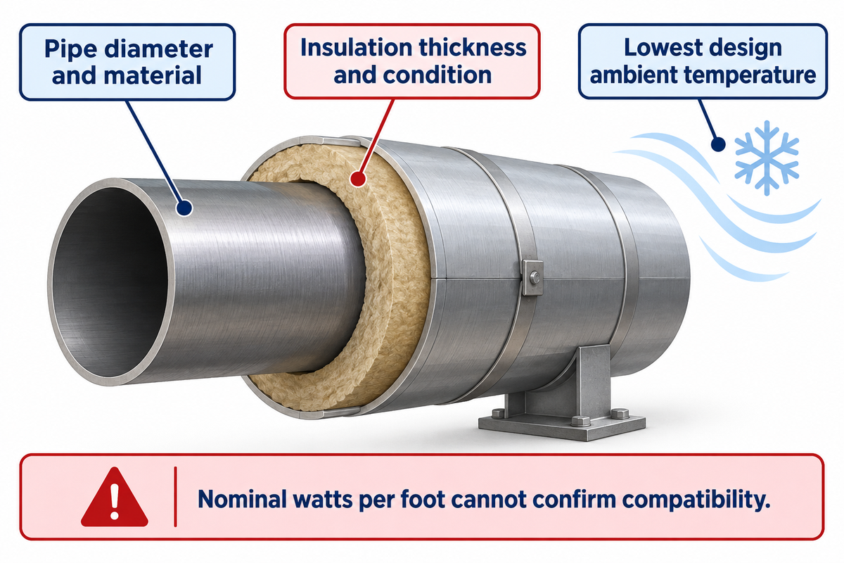
Heat trace sizing begins with heat loss at the required pipe temperature and the lowest design ambient temperature. All of the above (pipe diameter and material, insulation thickness and condition, local features, i.e. supports and valves, etc.) affect the calculation. Nominal watts per foot can’t confirm compatibility or adequate heating for an unknown pipeline.
Copy these inputs into a quote request. “Design-specific” means that the supplier must return a value or approved arrangement. It can’t be an acceptable blank in the finished specification.
| Parameter | Required value or range | Why it matters | How to verify |
|---|---|---|---|
| Duty and fluid | Freeze protection or process duty; fluid identity | Defines the temperature objective | Approved process requirement |
| Temperature limits | Maintain range and maximum exposure, °F or °C | A cleaning cycle may exceed normal operation | Separate powered and unpowered ratings |
| Pipe geometry and material | Diameter, length, material and fittings | Changes heat loss and compatibility | Drawing and pipe identification |
| Insulation | Material, thickness and weather covering | Wet or missing insulation defeats the assumed heat loss | Site inspection and product permission |
| Environment | Minimum ambient, exposure and area classification | Weather and hazardous areas affect selection | Site design basis |
| Electrical supply | Voltage, circuit length and cold-start condition | Starting current can constrain circuit layout | Exact-model design tables |
| Controls and access | Sensor locations, alarms and service openings | A warm sensor may miss a cold section | Reviewed control and maintenance plan |
Will heat trace melt PVC?
An unsuitable heater or an incorrect installation can damage plastic pipe. It’s recommended that heat cable, approved for the specific pipe material, be used with the approved attachment, control and insulation arrangement. No universal PVC wattage can be recommended for this guide. Allowable pipe temperatures and the heater’s local surface condition need to be considered.
An example of helpful, material-specific guidance is PPI MS-8 (2025), section 3.3.5. In its specification for PP-R and PP-RCT polypropylenes, it calls for exterior, plastic-compatible self-regulating tracing and a pipe surface limit of 150°F (66°C). That isn’t a PVC limit. A supplier has to evaluate the actual piping systems and the product rather than transfer this to another material.
Heat Trace Thermostat, Sensors and Electrical Protection
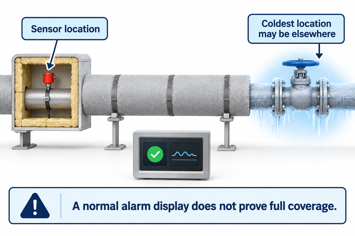
Temperature control, self-regulating output and electrical protection perform distinct functions. A controller responds to its sensor; a self-regulating cable responds to temperature locally, and protective devices respond to specified electrical faults. Selecting one doesn’t exclude the other two. The complete assembly should comply with the product instructions, electrical supply requirements and applicable installation requirements.
Does heat trace need a thermostat?
Many systems use a thermostat or controller, and Thermon’s installation guidance recommends thermostatic control for freeze protection and temperature maintenance. Depending on the product and design, an engineer may specify different limiter requirements for a stabilized design, but that shouldn’t be viewed as permission to omit necessary temperature control for self-regulating heat trace cable.
Adjust the setpoint within the approved design. Mounting a sensor at the wrong location won’t be compensated by an adjustable setpoint. Ask what pipe temperatures the sensor represents, which cold sections it monitors, and what happens after an alarm. For protection and cold start limits, a qualified designer will make the selection. For other process considerations, see pipe process heating and control.
The NRC’s Bulletin 79-24 records a revealing historical failure. In January 1979, a line at Davis-Besse Unit 1 froze during prolonged cold weather, with defective insulation contributing to the problem. It had redundant heat tracing and low-temperature alarms. Investigators found no apparent malfunction of those circuits, but their sensors weren’t at the coldest location. The lesson for a plant reviewing its design is about coverage: two functioning circuits don’t prove that every vulnerable point is warm. Trace the monitored location back to the physical pipe and its exposure, especially where local temperature drops may go undetected.
Heat Tracing vs Heating Blanket: Match the Geometry

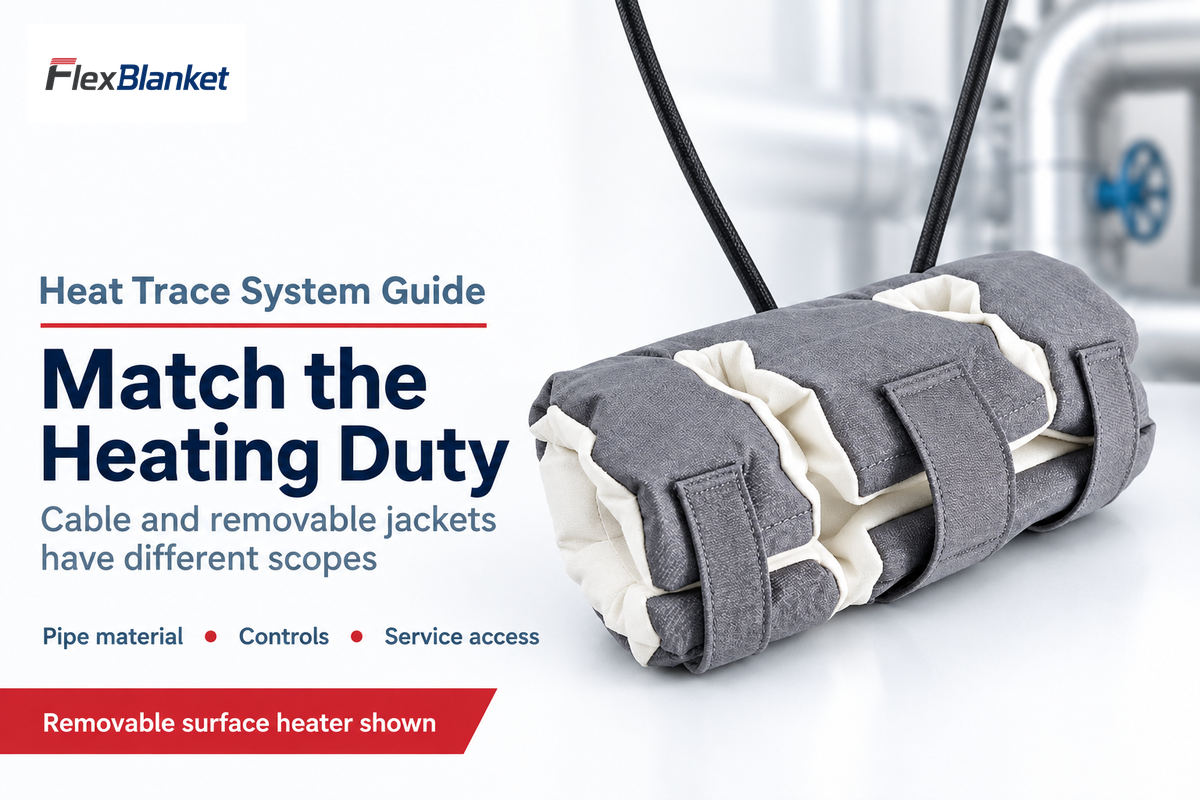
Cable follows a pipe route. A fitted electric heating blanket or jacket covers a defined surface. Geometry and service access therefore help screen the options. A long run and a frequently opened valve may require different treatment. Neither option is automatically cheaper, more energy-efficient, or approved for the same environment.
Ask how the heater is removed and restored, where the leads are located, and who checks it before restart. A removable passive insulation cover reduces heat loss; it isn’t the same thing as a powered jacket. A flexible hose or an IBC container also needs its own assessment rather than a design carried over from pipe heating.
FlexBlanket’s pipe and process heaters are removable surface-heating products. Its detailed heat trace versus heating blanket comparison covers that choice further. Be clear about distinct cable and jacket designs when requesting a combined arrangement.
Heat Trace Cost: Installed Scope and Running Energy
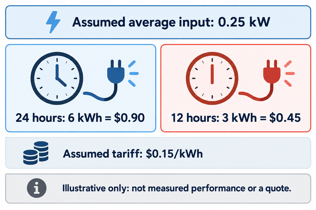
The installed cost of heat trace covers more than cable: connections, controls and protection, insulation, access, installation and commissioning. The running cost is impacted by average electrical input, operating hours and the energy tariff. A cable’s nominal output isn’t the measured annual electricity bill, especially if output varies with surrounding temperature.
For building projects, the ASPE discussion of additional heat tracing also highlights power to controllers and possible electrical-service upgrades. Include that scope when requesting a quotation.
Consider a hypothetical 50-foot line for a simple energy calculation. Assume its average electrical input is 5 watts per foot throughout the period, giving 50 × 5 = 250 W, or 0.25 kW. Over 24 hours, it uses 0.25 × 24 = 6 kWh. At an assumed tariff of $0.15/kWh, that costs $0.90 for the day. If it operates for only 12 hours at that same average input, the result is 3 kWh and $0.45. These are transparent assumptions, not a supplier quote, a local electricity rate or measured self-regulating performance. For budgeting, replace the average input and hours with the proposed operating profile; keep the cold-start calculation separate.
Daily energy cost = average input (in kW) × operating hours × tariff ($/kWh). Finance can use this equation, but procurement should compare the same installed scope. Maintenance should identify which items need to be removed and recommissioned during service. A low price for cable only may leave those responsibilities unpriced.
Funds should be provided for inspection and restoration after pipe work. Don’t promise a payback period unless both alternatives have comparable quotes, and similar assumptions and maintenance costs.
How to Install Heat Trace and Troubleshoot Cold Sections
A qualified installer should follow the exact cable system instructions, approved design, and applicable electrical requirements. The work includes checking the pipe, routing and attaching the heater, fitting the connections, and testing at the appropriate stages. On completion, the approved insulation should be restored. Commission the complete system, and retain records, rather than checking that power is available.
Isolate the circuit according to the site process. Use the specified termination kits and connector assemblies; an improvised connection isn’t an equivalent sealed termination. On completion, retain the circuit identification, routing diagram, control settings and the results of the manufacturer’s required tests. For removable items the pipe heating blanket installation guide covers jacket-specific planning.
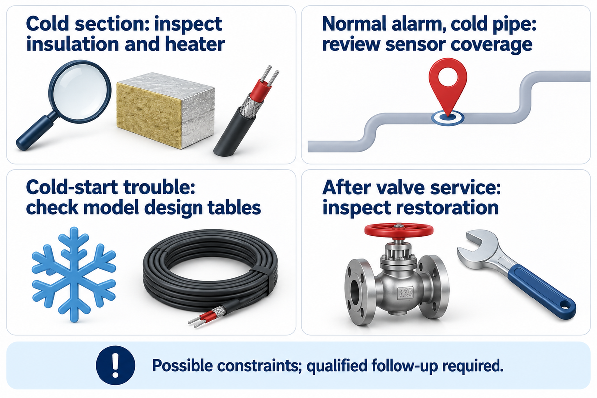
Process Heating’s report on circuit monitoring covers Thermon TraceNet Genesis functions. These are helpful in analyzing fault records, but the technician must still check the actual physical installation. Use the following map to assign checks and not to jump to conclusions about the cause of a symptom.
| Observed problem | Possible hidden constraint | Qualified follow-up |
|---|---|---|
| One cold section | Wet insulation, local heat loss or damaged heater | Compare route, insulation and prescribed test records |
| Normal alarm display, cold pipe | Sensor misses the vulnerable location | Review sensing coverage against actual exposure |
| Trouble at cold startup | Starting current or circuit-length constraint | Check exact-model cold-start design tables |
| Problem after valve service | Heating or insulation not restored correctly | Inspect restoration before returning the line to duty |
Industrial Heat Trace Suppliers: Match the Project Scope
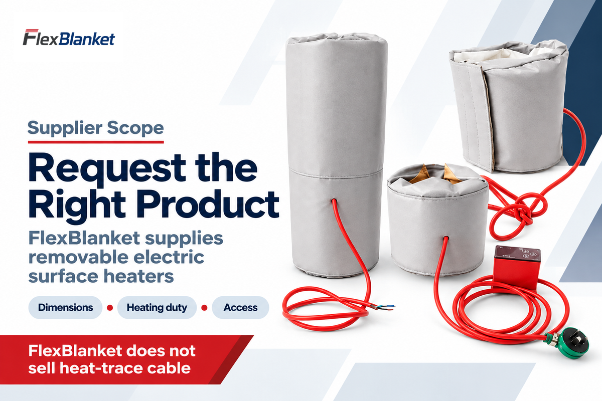
Compare heating solutions by what suppliers can document and deliver for the project: cable, controls, design support, installation, or fitted surface heaters. Thermon and DwyerOmega publish electric heat-tracing product information. FlexBlanket supplies removable electric surface heaters, and doesn’t sell heat-trace cable. These are different scopes of work and not a substitute supplier list.
Ask the proposed cable supplier to provide a model-specific design with limits on temperature, electrical supply, circuit layout and connection. High-temperature applications need the actual maintain and exposure ratings; a family name isn’t acceptable. Where hazardous areas are involved, request approval for the same equipment and the same installation conditions.
For shaped valves or vessels, give dimensions, duty, temperature limits and access with your request for custom heating blankets. If the need is for cable along a long pipe route, take your completed design input table to a heat tracing system supplier. This places responsibility clearly for the next quotation.
Heat-Tracing Outlook: Make Monitoring Useful for Maintenance
New requirements give an opportunity to integrate monitoring with maintenance. A dashboard is only useful if a circuit is identified and its heating duty checked. Specify handoff; buying more displayed data doesn’t mean pipe temperatures remain in the required range.
For trace heating systems, historical and fault analysis features of process control systems are documented in trade reporting and the 2020 Process Heating product notice. They shouldn’t be considered emerging trends. Ask what the system logs, who receives alarms, and whether drawings and previous results are available to the responding maintenance technician. Environmental conditions and insulation changes require physical presence.
Standards editions also deserve a deliberate check. The IEC/IEEE 60079-30-1:2025 public listing mentions a revised edition of electrical resistance trace heating in explosive atmospheres. A revised edition in itself does not set a local legal deadline to replace existing systems. The project team should identify the edition that is required by their jurisdiction, specification and equipment approval.
For standard industrial and commercial applications, the IEEE/IEC 62395-1:2024 scope is a different starting point; it does not cover explosive atmospheres. For these cases, you must consult the complete standard and product documentation to clarify design. Do not accept a summary of an article as the acceptance criteria.
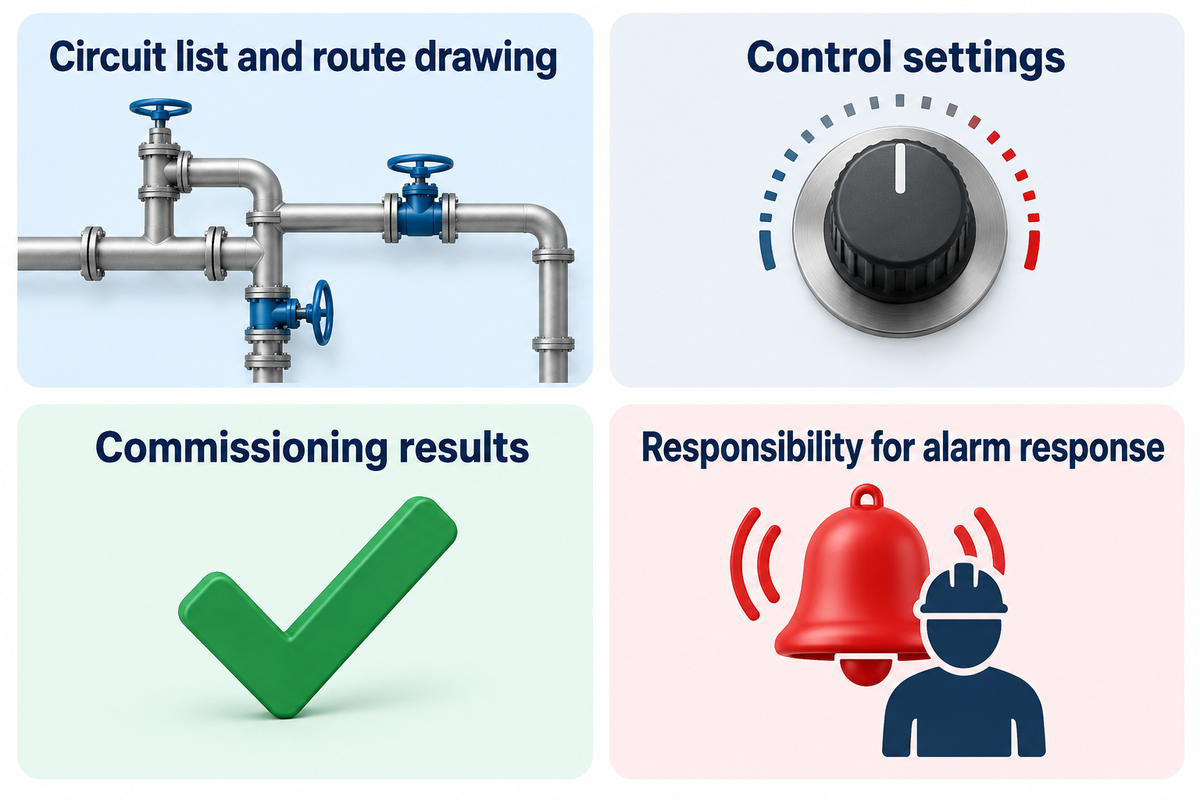
A practical handover package therefore should include a circuit list aligned to the route drawing along with control settings, commissioning results and responsibility for alarm response. Upon completion of work on the line, compare its restored state against the record. For the plant manager, this makes cold sections easier to assign; for maintenance it preserves the context for further investigation. From a procurement point of view, this gives a document to request prior to an order being placed.
Frequently Asked Questions
Does heat trace need to be insulated?
Industrial pipe tracing is commonly designed with insulation, but covering permission is product-specific.
Select the material, thickness and weather protection from the system design. Wet, missing or compressed insulation changes the assumed heat loss. Consumer heat tape needs particular care: CPSC guidance makes covering conditional on the manufacturer’s instructions. Don’t put a heater over existing pipe insulation or add an arbitrary covering to an unidentified product. Establish the exact installation requirements first.
“Do not cover the heat tape with insulation unless advised by the manufacturer.”
Can heat trace cable be spliced?
Some systems allow specified field splices; others restrict modification.
Identify the exact cable and approved kit before planning the work. The electrical connection, sealing, circuit length and area classification all need to remain within the installation instructions. A generic wire connector isn’t an equivalent substitute. If the product is supplied as a complete assembly, obtain its modification rules rather than assuming that a damaged section can be cut out and rejoined.
Can heat trace be exposed?
Outdoor exposure and operation without insulation are separate approval questions.
Sunlight, moisture, chemicals and uncovered use impose different conditions. An outdoor-rated jacket doesn’t automatically satisfy every one of them. Check the ratings of the cable, connections and complete arrangement. Pipe tracing designed with insulation may also have inadequate output when that insulation is removed. For a line concealed behind walls, include access and inspection requirements in the design before closing the enclosure.
Can heat trace be submerged?
Only use a product approved for the intended immersed application.
A weather-resistant jacket doesn’t establish approval for submerged end seals, connections or drinking-water contact. Confirm the complete arrangement before placing any heater inside water pipes or another liquid-containing system.
How long does heat trace last?
There is no service-life number that applies to every cable.
Exposure temperature, chemicals, moisture, installation damage and maintenance all influence performance. A warranty period isn’t a predicted replacement interval. Keep commissioning and periodic test records, inspect insulation and weather seals, and investigate changed readings or cold sections. Replacement should follow the product instructions and a qualified assessment of actual condition rather than a generic calendar age. If a line is opened for service, include the heater, seals and insulation in the return-to-service checks. An intact outer covering alone doesn’t prove the cable is sound, and a power indicator doesn’t prove the entire heated route is meeting its duty.
Is heat trace 120 or 240?
Products are available for different supply voltages.
Match the exact cable, controls and connection arrangement to the site supply. Use the correct voltage-specific output and circuit data rather than inferring compatibility from appearance.
Does heat trace use a lot of electricity?
Consumption depends on average input power and operating hours.
A self-regulating cable’s output changes with conditions, so nominal watts per foot isn’t a year-round energy meter. Insulation condition, ambient temperature and the control strategy also matter. For an operating site, measure energy over a representative period; for a proposal, request the stated operating assumptions. Keep the energy estimate separate from the cold-start current used in circuit design.
References & Sources
- ASPE: What Freeze Protection Is Needed in an Unheated, Open Parking Garage?, 2021; professional discussion of insulation and heating.
- Plastics Pipe Institute: MS-8, 2025, section 3.3.5; PP-R and PP-RCT model specification.
- NRC Bulletin 79-24, 1979; historical freezing and sensor-placement case.
- CPSC: Heat Tape Guidelines, 1996; consumer product-specific covering guidance.
- Process Heating: Controls to Manage Heat-Trace Circuit Performance, 2020; manufacturer product news, not independent performance testing.
- IEC/IEEE 60079-30-1:2025; public edition and scope listing for explosive atmospheres.
- IEEE/IEC 62395-1:2024; public scope for industrial and commercial applications.
Product examples are limited to the named manufacturers’ reviewed documentation. The energy calculation uses stated assumptions; no first-hand installation test or comparative performance measurement is claimed.