Get in touch with FlexBlanket Company

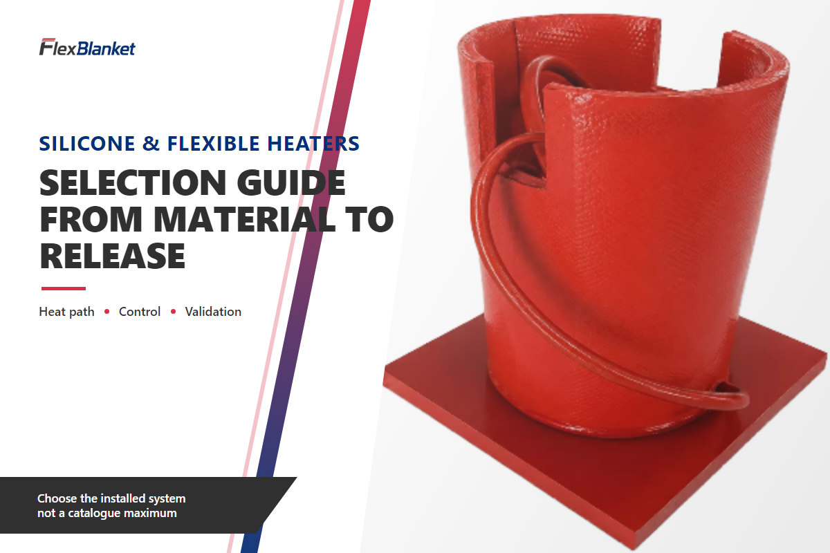
A Flexible Heater Selection Guide is a system-based method for choosing among Silicone & Flexible Heaters without treating a catalogue temperature or wattage as the design. Viewed as a system, the flexible heater sits beside the heated body, mounting layer, insulation, sensor, controller, wiring and acceptance evidence.
Whether a project is labelled aerospace, medical devices or industrial equipment, the application name does not establish thermal fit or approval; explicit mass, space, contamination and qualification constraints do.
Choosing the right flexible heater starts by naming the type of flexible heater, the heating needs and the evidence expected from the installed system. This selection guide treats material, circuit, mounting and temperature control as linked decisions rather than isolated product filters.
Four-lens decision
Select through thermal duty, physical fit, control objective and release evidence. Materials and circuits remain candidates until the heat path, mounting, sensing, safety boundaries and acceptance tests are defined. If one lens lacks evidence, the choice is qualified or blocked.
What Must a Flexible Heater Selection Guide Decide?
Useful guidance decides whether the proposed surface-heating system can be justified in its installed condition. Selection does not start by picking red silicone, amber polyimide or a circuit pattern. Plant engineering first defines the thermal job. Equipment design confirms contact and geometry. Controls identifies the feedback target. Quality and procurement define the evidence needed to release the build.
Using the 4-Lens Heater Fit Scorecard puts those responsibilities into one review. Rows marked “Ready” have current evidence. “Qualified” means an assumption is visible and someone owns the verification. “Blocked” means the missing input can change fit, safety or thermal performance.
| Decision lens | Question to close | Evidence | Blocked when |
|---|---|---|---|
| Thermal duty | What must be heated, from what start condition, to which operating window? | Duty statement, losses, insulation and allowed time | Heat requirement is only a catalogue guess |
| Physical fit | Can the heater maintain the required contact without damaging the assembly? | Drawing, substrate, surface finish and mounting plan | Geometry or service access is unknown |
| Control objective | Is the controller regulating heater, surface or process temperature? | Sensor location, lag review and protection logic | Displayed value has no defined relationship to the duty |
| Release evidence | What must pass before the assembly is accepted? | Electrical tests, thermal map, approvals and records | Acceptance means only “it became warm” |
Compare Material Endurance Without Turning It Into an Assembly Ceiling
Materials such as silicone rubber, polyimide film and polyester are insulation-system candidates, not three fixed performance packages. Adhesive, conductor, lead termination, substrate, mounting and qualification evidence change the useful operating envelope. If a specification uses “Kapton,” ask which exact polyimide film and complete heater construction it means.
Material endurance evidence still matters. IEC 60216-1:2025 describes ageing procedures that derive thermal-endurance characteristics from time to a predetermined property change. Such evidence is not the maximum operating temperature or service life of a completed heater. Interfaces, conductors, terminations, mounting and the actual duty cycle add further limits.
This Material-Circuit-Mount Crosswalk keeps Silicone & Flexible Heaters useful as an umbrella topic while forcing each choice back to evidence. Read every cell as “candidate when,” “avoid when evidence shows,” or “verify before release.”
Search language often splits the same engineering task into polyimide heaters, a flexible strip heater, a flexible silicone heater, etched foil heaters or a bendable heating element. Related searches also use “Polyimide flexible heaters,” “Silicone Flexible heater,” and “Flexible Strip Heaters.” Treat those phrases as discovery labels; the installed duty still decides the candidate.
| Decision input | Silicone candidate | Polyimide candidate | Evidence before release |
|---|---|---|---|
| Surface geometry | Candidate for larger or irregular surfaces | Candidate where a very thin profile matters | Drawing, bend condition and contact plan |
| Thickness and mass | Verify the installed stack | Candidate for mass-sensitive assemblies | Complete stack thickness and weight limit |
| Moisture or chemicals | Candidate after construction-level review | Avoid assumptions based on film alone | Exposure list and complete-assembly test scope |
| Mechanical handling | Verify tear, lead and edge protection | Verify fold, crease and lead-zone limits | Handling and installation procedure |
| Repeated flexing | Qualification required | Qualification required | Application-specific bend and thermal-cycle test |
| Permanent installation | Bonded or factory-integrated candidate | Thin bonded candidate | Surface preparation and adhesive evidence |
| Service removal | Mechanical retention may be considered | Avoid assuming an adhesive is reusable | Removal, inspection and reinstatement plan |
| Heat distribution | Pair material with a released circuit pattern | Pair material with a released circuit pattern | Temperature map and boundary conditions |
| Qualification records | Verify the quoted construction | Verify the quoted construction | Revision-bound material, electrical and environmental evidence |
Choose Etched Foil or Wire Wound by Geometry and Heat Distribution
Circuit construction changes how resistive heating elements distribute power across the available area. Etched foil supports deliberately patterned paths, local heat-density changes and multi-zone heating. Wire-wound construction can follow different fabrication routes for larger or irregular shapes. Neither option is automatically more durable, efficient or uniform in every installed system.
During fabrication review, mark cutouts, fasteners, keep-out zones, lead pads, edge-loss regions and required acceptance points on the same drawing. A compact plate may support a profiled foil circuit, while a large irregular vessel may create a different wire-routing problem. In either case, ask the supplier to return the circuit drawing, nominal resistance and temperature-map plan rather than accepting a construction label alone.
Heating element layout is therefore an engineering input, not a label to choose after the material. Pattern, spacing, edges and lead zones all influence where electrical power enters the thermal stack.
Research on a peer-reviewed flexible microheater found that geometry, input power, substrate and boundary conditions changed temperature distribution. Its PET, graphene, copper wire, dimensions and voltages do not describe an industrial silicone heater. One narrower lesson transfers: circuit shape cannot be judged apart from the surrounding thermal system.
Is etched foil always better than wire wound?
No. Etched foil is a strong candidate when patterned distribution, a thin profile or defined zones matter. Wire wound may be a candidate for other sizes, shapes or fabrication constraints. Buyers still have to close geometry, element spacing, lead routing, handling, mounting and the acceptance temperature map. “Foil” or “wire” alone is not a release decision.
Release Watt Density Against the Installed Heat Path
Watt density describes electrical loading over the heating area. It does not prove that the installed stack can move that heat output into the load without a damaging local temperature. Heat path includes the element, dielectric, adhesive or mounting layer, substrate, product mass, insulation, ambient losses and control response. Energy efficiency cannot be judged from nominal watt density alone.
Uniform heat depends on heat transfer through that entire stack. A single nominal area value cannot show what happens at cutouts, edges, fasteners or trapped air.
Arithmetic is simple; release is not. For an illustrative 240 W heater over 0.06 m², the nominal loading is 240 ÷ 0.06 = 4,000 W/m², or 0.4 W/cm². That example is not a recommended value. It becomes useful only when the substrate, contact, losses, target temperature, circuit limit and acceptance map are supplied.
Heat-path release inputs
- Heated area, substrate material, thickness and surface condition
- Starting, target and ambient conditions
- Heat-up or temperature-maintenance duty
- Insulation stack and exposed losses
- Available voltage, current and circuit protection
- Control target and over-temperature response
- Acceptance points across the heated surface
How do I calculate flexible-heater watt density?
Divide nominal heater power by active heated area, using consistent units. Then stop treating the result as a recommendation. Engineers or qualified suppliers must compare it with the complete heat path, control objective and worst credible boundary condition. Loading that works on a thick aluminum plate may create a hot spot over an air gap, cutout or low-conductivity surface.
Mounting, Insulation and Lead Exit Are Design Inputs
Permanent bonding, pressure-sensitive adhesive, clamping, mechanical retention and factory integration create different contact, service and inspection conditions. Applications requiring freeze protection, high operating temperatures or frequent access can lead to different mounting choices. Mounting method controls whether an air gap can form, whether the heater can be replaced, and what preparation or curing process is required.
Installation conformability is not in-service flex endurance. Bending once around a housing does not qualify a heater for repeated movement. Research on a different graphite-cellulose heater treated bending and heating-cooling cycles as separate tests. Its cycle counts, temperatures and materials do not transfer; the useful lesson is to specify a cyclic test when the application actually moves.
Three situations illustrate the split. On a flat aluminum plate, a low-profile bonded stack may work after surface preparation is defined. For an irregular serviceable vessel, removal and reinstatement may matter more than minimum thickness. Under vibration, lead exit, strain relief and connector temperature can limit an otherwise well-fitting heater body.
Place the Sensor Around the Feedback Objective
Heater temperature, heated-surface temperature and process temperature are different variables. Convenience can therefore produce the wrong feedback point. Controller action follows what the sensor represents; it cannot correct a thermal lag or gradient that the measurement never sees.
Precise temperature control begins by naming that variable and assigning a separate protection function when one sensor cannot serve both process accuracy and local heater safety. Consistent temperature at the controller is not proof of uniform temperature across the heated surface.
NASA’s thermal-control reference describes resistance heaters controlled with thermostats or temperature sensors as part of active thermal control. What transfers is the feedback architecture, not a spacecraft temperature, voltage or construction.
Where should a flexible-heater sensor be installed?
Place it where it can represent the variable the controller is meant to regulate, then test the lag and gradient between that point and the actual duty. Near-heater sensing can protect the element while missing a slow process temperature. Process sensing can represent the material while reacting too slowly to protect a local heater hot spot. Many systems need separate control and protection functions.
Keep Five Safety and Approval Gates Separate
After the feedback target is defined, safety evidence determines whether that control plan can be installed. Five gates prevent one marketing label from carrying responsibilities it does not cover. Buyers should close every gate for the complete assembly, including leads, connectors, controller and surrounding equipment where applicable.
| Gate | Evidence question | Consequence if open |
|---|---|---|
| Chemical review | What do the actual safety data sheet and exposure conditions require? | Material choice remains unqualified |
| End-use electrical approval | Is the equipment suitable, installed and marked for its identified use? | Completed installation cannot be released |
| Hazardous location | What is the documented area classification and required equipment approval? | Equipment selection stops |
| Ingress scope | Which complete assembly and test boundary does the code cover? | A heater-body claim cannot release the system |
| Contact-burn risk | Who can touch the surface, for how long and under which conditions? | Access or guarding remains unresolved |
OSHA’s mandatory Safety Data Sheet Appendix D provides chemical information separately from hazardous-location requirements. OSHA 1910.307 requires classified areas to be considered individually and documented.
OSHA 1910.303 adds the broader end-use installation boundary: approval, suitability, durability, wire-bending space, insulation, heating effects, markings, mounting and the operating environment all matter. None of these pages certifies a particular FlexBlanket product or classifies a reader’s site.
Ingress language does not replace those gates. Nor does ASTM C1055 create one universal touch-safe temperature; contact time, surface configuration and the accepted injury criterion change the assessment.
Stop and escalate
Pause selection when the process chemistry is unknown, the location may be classified, an accessible hot surface lacks a contact-risk decision, the complete electrical assembly has no approval path, or over-temperature protection is undefined.
Commission With a Test–Monitor–Document Loop
Once safety and approval gates are defined, commissioning tests whether they hold under stated conditions. The method is not heater-specific, but it is established practice. The U.S. Department of Energy commissioning process connects functional testing, monitoring, result analysis, corrections, retesting and final documentation.
- Define acceptance criteria and the evidence owner.
- Inspect mounting, wiring, insulation, sensors and protection.
- Run functional tests under stated boundary conditions.
- Monitor heater, surface and process temperatures where the duty requires them.
- Record deviations, assumptions and corrective actions.
- Retest any changed condition rather than accepting the old result.
- Hand off drawings, settings, readings and future inspection points.
This loop is an adapted buyer framework, not a heater-specific legal procedure. Its value is traceability: when a thermal map fails, the team can see whether the change involved contact, insulation, control, wiring or the acceptance method.
Diagnose Selection Mismatches Before Replacing the Heater
Poor results do not automatically mean the heater body is defective. Start with the mismatch between expected evidence and observed behavior. De-energize and follow site safety procedures before touching wiring, insulation or the heater assembly.
| Observed mismatch | Evidence gap to test first | Do not assume |
|---|---|---|
| Warm display, cold process | Sensor target, process lag and heat path | The controller display equals process temperature |
| Hot center, cool perimeter | Circuit geometry, edge loss, contact and insulation | More total power will correct distribution |
| Repeated over-temperature trip | Local contact, protection sensor and controller settings | The trip should simply be raised |
| Slow heat-up after a change | Insulation, mounting, substrate or process mass revision | The original calculation still represents the stack |
| Lead or connector distress | Exit temperature, strain relief, current and connection quality | A visually intact heater body releases the assembly |
Build the Surface-System Evidence Packet Before Requesting a Quote
Custom heating and equipment heating quotations become comparable only when suppliers receive the same duty, physical boundary, control objective and acceptance scope. This Surface-System Evidence Packet is a handoff record, not a promise of heating performance.
| Packet field | What to record | Primary owner |
|---|---|---|
| Drawing | Heated area, cutouts, edges and lead zone | Equipment design |
| Substrate | Material, thickness, finish and allowed attachment | Mechanical engineering |
| Thermal duty | Start, target, ambient, time and maintenance window | Plant engineering |
| Loss assumptions | Insulation, exposed area, airflow and interfaces | Thermal engineering |
| Electrical supply | Voltage, phase, current limit and protective devices | Electrical engineering |
| Material and circuit | Candidate construction and the evidence still required | Supplier + design |
| Mounting | Bond, clamp, retention, preparation and replacement route | Manufacturing engineering |
| Sensor target | Heater, surface or process variable and expected lag | Controls |
| Environment | Moisture, chemicals, vibration, washdown and access | Plant + safety |
| Approval path | End use, area classification, ingress and documentation | Quality + safety |
| Qualification | Static fit, bending, thermal cycling and environmental tests as applicable | Quality |
| Acceptance | Electrical results, temperature map, records and revision | Quality + procurement |
Finance should resist comparing unit prices until the scope matches. Quality should define records before the build rather than after a dispute. Maintenance should state access and replacement needs while the geometry can still change. When the packet is ready, the commercial handoff is FlexBlanket silicone and flexible heater solutions.
2026 Outlook: Evidence Before Higher Catalogue Limits
Evidence architecture is the defensible change, not a market-growth percentage. IEC/IEEE 62395-2:2024 frames design, installation, maintenance and repair as a system lifecycle. IEC 60216-1:2025 makes material endurance explicitly time- and property-dependent. For a 2026 project, buyers should request a linked set of material, heat-path, control, installation and release records instead of rewarding the highest isolated catalogue number.
“System design, installation, maintenance and repair.”
— IEC/IEEE 62395-2:2024 scope
For 2026 procurement, the practical outlook is narrower: compare suppliers on revision-bound evidence and keep product, specification and quotation questions on the commercial solution path.
Frequently Asked Questions
Which flexible-heater material should I choose?
Choose the material only after defining the installed stack.
Silicone rubber may be a candidate for larger, irregular or mechanically demanding industrial assemblies. Polyimide may fit where a thin, low-mass construction matters. Polyester can suit lower-temperature or cost-sensitive designs when the complete construction supports it. Verify adhesive, conductor, leads, mounting, environment and qualification evidence. Also distinguish a material thermal-endurance characteristic from the assembled heater’s allowable operating condition. Procurement should ask which exact construction was tested, which property defined end of life, and which interfaces remain outside that evidence. If the heater moves in service, add application-specific bend and thermal-cycle tests rather than assuming that installation flexibility proves cyclic durability.
How do I calculate flexible-heater watt density?
Divide nominal power by active area, then validate that result against the complete heat path, contact, losses, sensor target, over-temperature protection and credible boundary conditions before release.
Calculation yields watts per square metre or watts per square centimetre. That number does not show whether the installed surface can absorb and distribute the heat. Release it only after reviewing substrate, contact, cutouts, insulation, ambient losses, available circuit, sensor target and over-temperature protection. Confirm the choice with a temperature map taken under stated boundary conditions, including any credible air gap or edge-loss condition.
Where should the temperature sensor go?
Put the sensor where it represents the intended feedback variable, then test the lag and gradient from that point to the actual heater, surface or process duty under stated operating conditions.
First decide whether the controller regulates heater, surface or process temperature. Next, map the gradient and lag from that point to the real duty during warm-up and steady operation. Near-heater sensing may protect the element while missing a slow process response. Process sensing may represent the material but react too slowly to a local heater hot spot. If those risks cannot be served by one measurement, specify separate control and over-temperature protection sensors, then document which one owns each shutdown or alarm. During commissioning, compare the sensor reading with independent surface or process measurements at the stated acceptance points. Record the conditions, not only the final setpoint, so later insulation or mounting changes can be evaluated against the same baseline.
Does an IP rating approve a heater for a hazardous area?
No. Ingress protection and hazardous-location approval answer different questions.
Ingress codes address a defined dust or liquid test scope. Hazardous-location selection depends on documented classification, material, equipment approval and temperature marking. Chemical compatibility and end-use electrical approval remain separate.
What should I send a flexible-heater supplier?
Send a revision-controlled surface-system evidence packet.
Include the drawing, substrate, start and target temperatures, ambient conditions, duty, insulation, electrical supply, mounting preference, lead zone, sensor target, controller and protection logic, environment, area classification, relevant approvals, qualification tests and acceptance records. Mark every value as measured, calculated or assumed, and name the owner of each open item. State whether the heater bends only during installation or repeatedly in service. Quotations become easier to compare when every supplier receives the same boundary and returns evidence against the same revision.
Release rule
Choose the flexible-heater configuration that can be justified in the installed system. Close the thermal duty, physical fit, control objective and evidence plan before rewarding a catalogue maximum.
References & Sources
- IEC/IEEE 62395-2:2024 — system lifecycle and scope.
- IEC 60216-1:2025 — material thermal-endurance ageing procedures.
- OSHA 1910.303 — approval, examination, installation and use of electrical equipment.
- OSHA 1910.307 — hazardous classified locations.
- OSHA 1910.1200 Appendix D — mandatory safety data sheet structure.
- U.S. Department of Energy commissioning process.
- NASA thermal-control reference — heater, sensor and controller architecture.
- ASTM C1055-20 — contact-burn assessment for passive heated surfaces.
- Design and Thermal Analysis of Flexible Microheaters — mechanism-level geometry evidence.
- Bending-tolerant flexible-heater study — example of separate cyclic qualification.