Get in touch with FlexBlanket Company

Heat Transfer Equation: Energy, Heat Flow and Heating Time

A heat transfer equation connects thermal energy with a temperature change or a rate of heat flow. Use Q = mcΔT for sensible heat energy, Q̇ = kAΔT/L for steady conduction through a flat wall, and Q̇ = hAΔT for surface convection. Radiation uses absolute temperatures raised to the fourth power. First determine whether your answer should be in joules, watts, or watts per square meter.
Heat transfer equation selector: start with the units
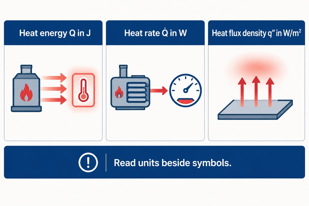
Energy determines the amount of heat that moves; heat transfer rate determines the speed at which heat is transferred per unit time. Heat flux includes the surface area through which that transfer occurs. Considering the water in a bucket: volume, filling rate and flow through each square centimeter describe different things. The same distinction applies here, so you do not mix joules with watts.
The 3-Quantity Equation Selector below groups equations by their output. Q means heat energy in J, Q̇ means heat rate in W, and q″ means heat flux density in W/m². Some references use q for a rate and others for flux, thus it is best to read the units beside the symbols.
| Question | Equation | Result | Main condition |
|---|---|---|---|
| Energy to change a fixed mass’s temperature? | Q = mcΔT | J | Constant specific heat; no phase change |
| Energy for a phase change? | Q = mℓ | J | Latent heat ℓ matches material and conditions |
| Average rate over a time interval? | Q̇avg = Q/Δt | W | Q is the energy transferred during that interval |
| Steady conduction through a plane wall? | Q̇ = kAΔT/L | W | One-dimensional flow; constant k |
| Exchange between a surface and fluid? | Q̇ = hA(Ts − Tbulk) | W | h fits the geometry and flow regime |
| Radiation to large surroundings? | Q̇ = εσA(Ts4 − Tsur4) | W | Absolute temperatures; uniform surroundings |
| Transfer through a series thermal path? | Q̇ = ΔT/Rtotal = UAΔT | W | Consistent geometry and temperature endpoints |
| Heat carried by a steady flowing stream? | Q̇ = ṁcp(Tout − Tin) | W | Sensible heating; negligible work and kinetic-energy change |
| Heat rate per unit area? | q″ = Q̇/A | W/m² | Use the area through which that heat flows |
Here, m is mass, c is specific heat capacity, A is area, L is wall thickness and ṁ is mass flow rate. The remaining coefficients are explained in their sections. Choosing the heating equipment comes after this calculation; the separate guide to industrial heating methods compares those options.
Heat energy versus heat transfer rate
One watt is equal to one joule per second. A fixed mass requires energy to change temperature, and the time required depends on the rate of net energy delivery. With approximately constant specific heat and no phase change, Q = mcΔT calculates that energy. The equation does not contain a time variable, so the duration cannot be determined by it alone.
The BIPM summary of SI units defines joule and watt in a consistent manner. With m in kg, c in J/(kg·K) and ΔT in K, the result is J. Divide by the time interval for average watts; use dQ/dt for an instantaneous rate, which can change during warming.
For a fixed temperature rise between different temperatures, doubling the mass doubles the amount of heat required. Doubling the available net power instead shortens the ideal heating time. Neither change means the specific heat of the material has changed. During melting or boiling, energy can transfer between hot and cold regions without a temperature rise. Split the calculation into sensible heating and latent heat, as in OpenStax’s calorimetry treatment.
One unit system must be kept constant for every substitution. A value in British thermal units cannot be directly added to joules, and hours must be converted to seconds when dividing joules to obtain watts.
Conduction: Fourier law through a wall
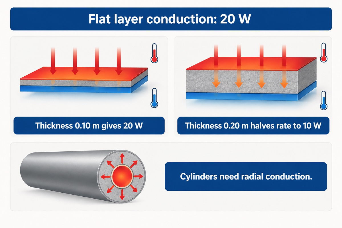
For an assumed flat layer with k = 0.04 W/(m·K), area 2 m², thickness 0.10 m and a 25 K surface temperature difference, steady conduction is 20 W. Heat flux is 10 W/m². This example assumes constant conductivity, one-dimensional heat flow, and fixed temperature on the two wall faces.
What is the Fourier equation for heat conduction?
As mathematically mentioned, Fourier’s law takes the form of Q̇ = −kA(dT/dx) in 1 dimension. The proportionality constant for conduction heat flow is expressed by the symbol k. The negative sign makes heat flow toward the colder side, when x increases, towards higher temperature. For a constant-k plane wall, the expression reduces to Q̇ = kA(Thot − Tcold)/L, the OpenStax slab-conduction relation.
Substitution: Q̇ = 0.04 × 2 × 25 / 0.10 = 20 W.
Comparing two similar flat insulation layers, suppose thickness is increased from 0.10 m to 0.20 m. Increasing thickness from 0.10 m to 0.20 m halves the rate to 10 W when conductivity, area and face temperatures stay unchanged. Area plays an important role in heat flow. This is why transfer is directly proportional to area and inversely proportional to thickness.
A cylinder requires a radial conduction relation; inserting pipe-wall thickness into the flat-wall equation may give a wrong answer because the area changes. Contact gaps add resistance. The law of heat conduction describes transfer through a substance, including stationary fluids and other media, rather than through metals and other solids.
Convection: finding the heat transfer coefficient
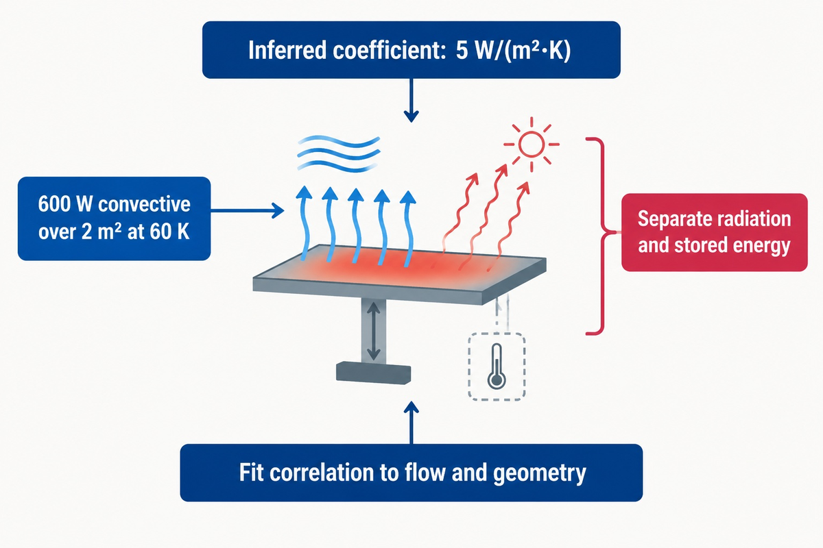
If a test separates 600 W of convective heat transfer from other heat paths over 2 m² at a 60 K surface-to-fluid difference, the inferred coefficient is 5 W/(m²·K). This assumed example illustrates h = Q̇conv/(AΔT). The coefficient shows that the surface and the fluid flow condition is more dominating than the fluid alone.
How to find the heat transfer coefficient?
Determine the coefficient from a correlation, experiment or validated thermal model based on the geometry and flow condition of the problem. Then apply Newton’s law of cooling, Q̇conv = hA(Ts − Tbulk), where Ts is the temperature of the surface. The MIT convection and conduction notes show this relationship.
“finding the heat transfer coefficient is a difficult problem”
Calculation: h = 600 / (2 × 60) = 5 W/(m²·K). Replacing that 600 W with the heater’s electrical rating would assign radiation, support conduction and stored energy to convection as well. A measured total input requires an energy balance to determine a convective heat transfer coefficient.
Motion of the fluid modifies the near-wall temperature gradient. Natural convection is typically caused by buoyancy, which occurs due to warming, and creates regions of different densities, or a fan or pump creates forced flow. An appropriate correlation must be fit to the actual combination of flow and geometry. For a finite tank, it is better to consider the changing bulk-fluid temperature, Tbulk(t), as opposed to treating the liquid as an unchanging cold reservoir.
Radiation: use absolute temperature
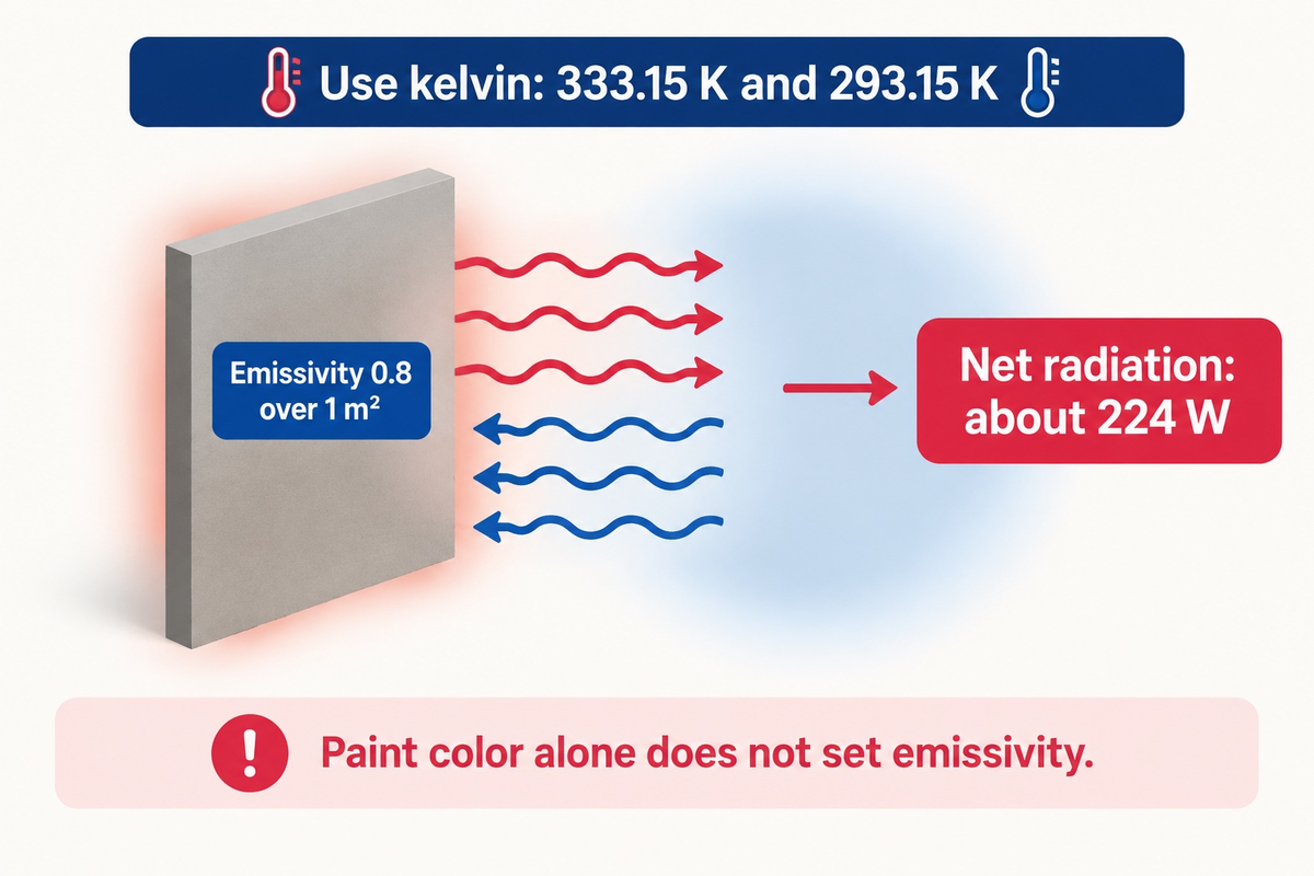
For an assumed emissivity of 0.8 and area of 1 m², a 60 °C surface radiates approximately 224 W net to large uniform surroundings at 20 °C. The calculation assumes 333.15 K and 293.15 K. Entering Celsius values directly to the fourth power gives a wrong, physically incorrect, result.
For the surface-to-surroundings approximation, the Stefan-Boltzmann law provides Q̇rad = εσA(Ts4 − Tsur4) with a positive outward flow. The NIST Stefan-Boltzmann constant is σ = 5.67 × 10⁻⁸ W/(m² K⁴).
Substitution: 0.8 × 5.67 × 10−8 × 1 × (333.154 − 293.154) = 223.78 W.
Thermal radiation can transport energy in the form of electromagnetic waves (including infrared) and can even cross a vacuum. An ideal black body absorbs incident radiation and loses energy at the blackbody rate and is therefore a perfect absorber and emitter. A real surface’s emission is characterized by its emissivity; paint color alone is not sufficient to assign an infrared emissivity.
Radiation between two surfaces of finite size requires consideration of view factors and both surfaces’ properties. The surroundings temperature is a radiative boundary which may be different from the surrounding air temperature. Hence, a radiant panel can lose energy by radiation and convection at the same time; their rates are separate terms in the energy balance.
Overall heat transfer coefficient and thermal resistance
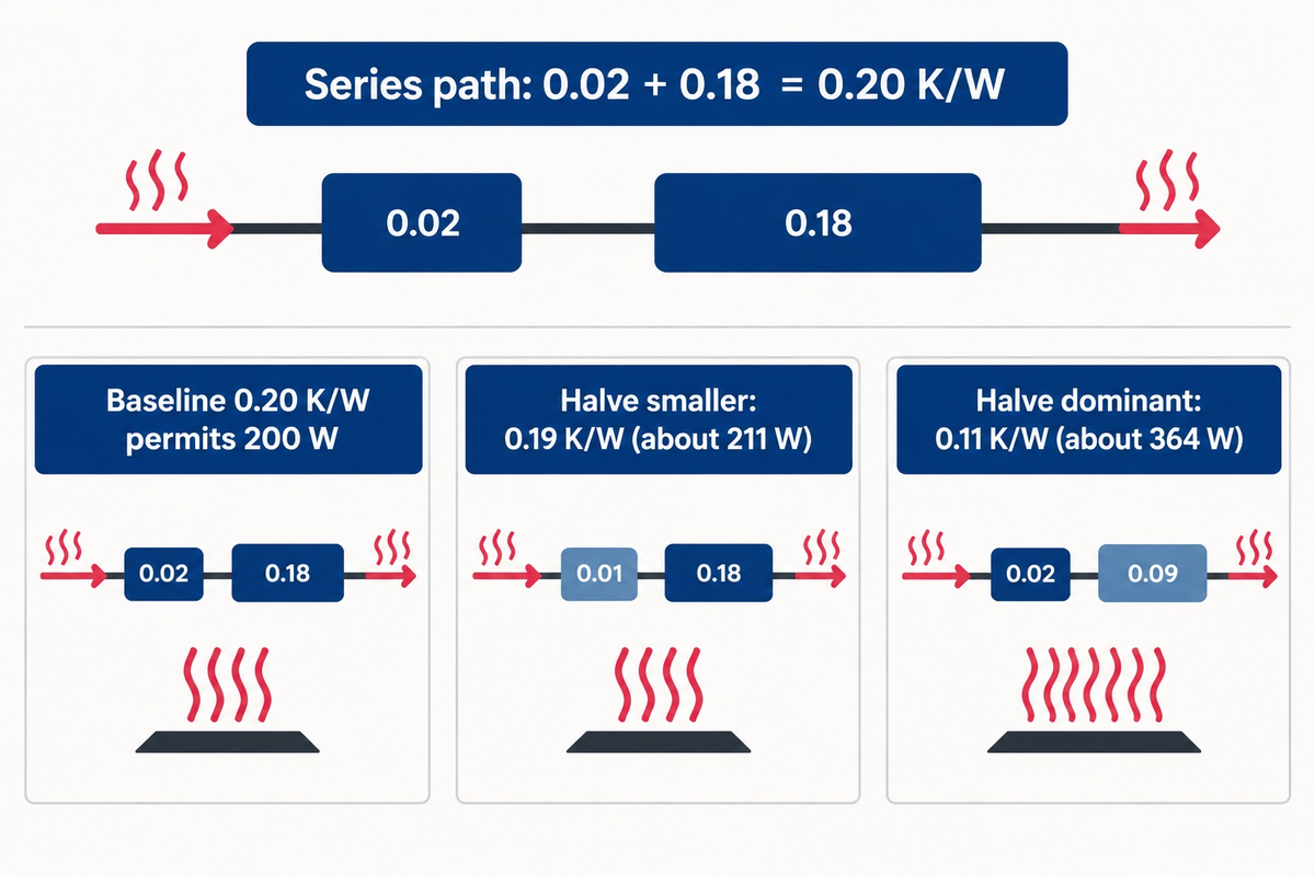
In series, the total thermal resistance is the sum of the individual resistances. Total resistance R in K/W gives Q̇ = ΔT/R; an overall coefficient U in W/(m²·K) gives Q̇ = UAΔT. For the same end points and area, UA = 1/R. A low-K material or fluid film may dominate a high-K material assembly.
Example heat path: heater surface → contact resistance → wall conduction → inner fluid film → bulk liquid.
Contact needs a measured or appropriate estimated resistance. Wall resistance is L/(kA). Fluid-film resistance is 1/(hA).
Assume two series resistances of 0.02 K/W and 0.18 K/W across a 40 K difference. Their total, 0.20 K/W, permits 200 W. Halving the smaller resistance gives 0.19 K/W and about 211 W. Halving the larger one instead gives 0.11 K/W and about 364 W. These assumed values show why changing the dominant barrier has a larger effect at the same driving temperature.
The MIT series-resistance model combines wall and convection resistances. Keep total R separate from area-normalized resistance R″ = L/k in m²·K/W: q″ = ΔT/R″ and U = 1/R″. Thermal resistivity, 1/k, has units m·K/W. For independent parallel paths between the same temperatures, the conductances add: 1/Req = Σ(1/Ri).
For a stable heat exchanger flow rate, Q̇ = ṁcp (Tout − Tin) balances sensible energy transported by the fluid. It neglects shaft work and changes in kinetic and potential energy. A separate UA relation describes transfer and requires appropriate mean driving-temperature difference. Arbitrary inlet temperatures cannot replace that mean; phase change requires an enthalpy balance.
Transient heat equation: when temperature changes with time
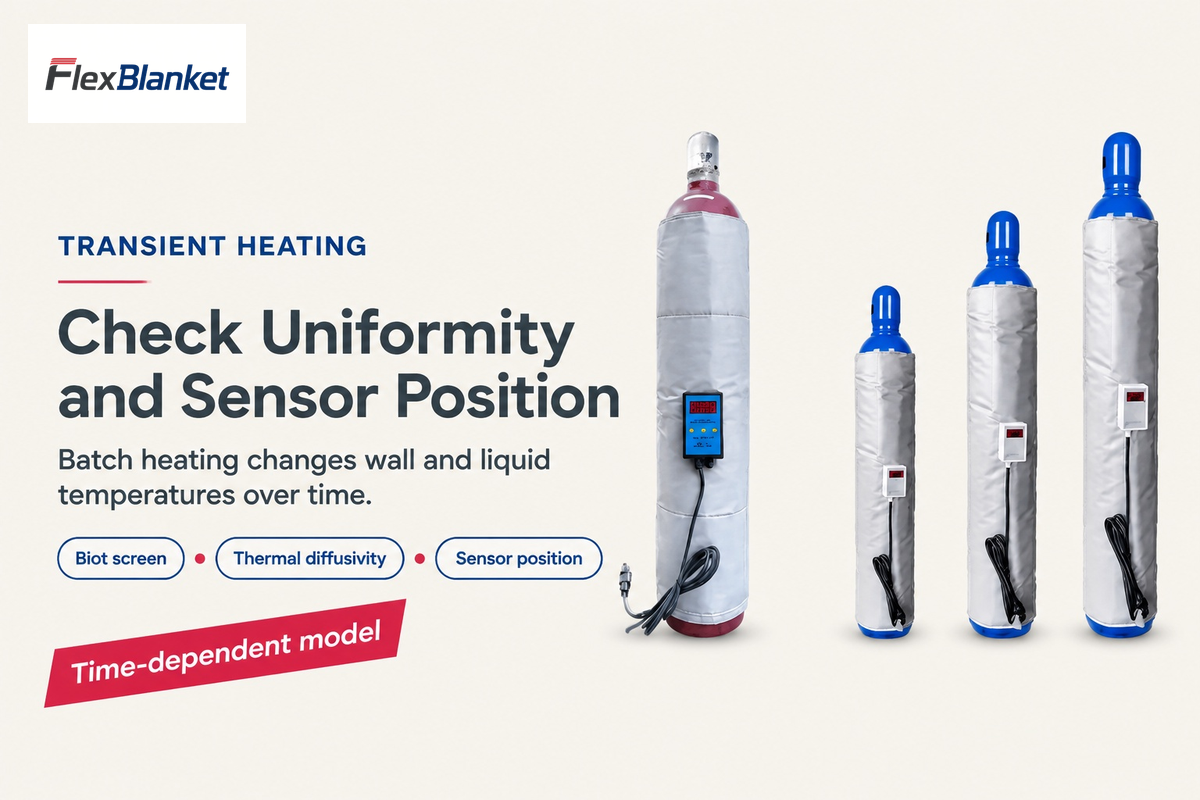
A Biot number of roughly 0.1 or less is standard criteria for treating a solid as nearly uniform in temperature during heating or cooling. It compares internal conduction resistance with external convection resistance. A single-temperature model can work for time dependent energy storage; larger internal gradients will require a spatially distributed model.
For a stationary, homogeneous solid with constant properties and no internal heat generation, the one-dimensional heat equation is ∂T/∂t = α∂²T/∂x², where α = k/(ρc) is thermal diffusivity in m²/s. Initial and boundary conditions complete this differential model.
The SFU transient-conduction lecture uses Bi = hLc/k with Lc = V/A. The South Carolina solid-conduction lecture describes a conservative full-radius screen for cylinders and spheres. State the length convention before comparing Bi values.
A liquid tank needs its own mixing assumption or a flow model. The Biot criterion for solids does not ensure uniform temperature for liquids. Fixed-ambient exponential cooling assumes a constant temperature of the surroundings. During batch heating, both the wall and liquid temperatures can change. When choosing temperature sensing and control the position of the sensors can be critical.
Heating a water tank: from energy to power
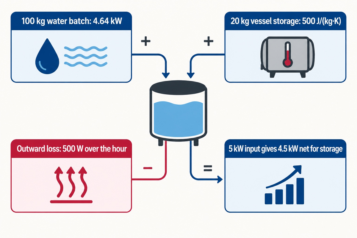
Heating an assumed 100 kg water batch from 20 °C to 60 °C in one hour requires about 4.64 kW delivered to the water, using constant cp = 4180 J/(kg·K). This is a sensible-energy estimate for well-mixed liquid near atmospheric pressure. Vessel heating and environmental losses may require a larger input of heat.
That specific heat is a rounded room-temperature approximation. Pátek and colleagues’ water-property paper, Table 8, gives 4181.44618 J/(kg·K) at 25 °C and 0.1 MPa. If we wish to determine the value of cp with greater accuracy within the temperature range, we should use temperature-dependent properties or an appropriate mean rather than simply treat a point value as exact.
Water Energy: Qwater = 100 × 4180 × (60 − 20) = 16,720,000 J = 16.72 MJ
Average net power: 16,720,000 / 3600 = 4644 W
Now add an assumed 20 kg vessel with specific heat 500 J/(kg·K), also warming by 40 K, and an assumed average outward heat loss of 500 W over the hour. Take the boundary around the vessel and its contents, with all the heat supplied entering that boundary. No extra efficiency divisor is applied to losses already counted.
| Term | Calculation | Energy | One-hour average |
|---|---|---|---|
| Water storage | 100 × 4180 × 40 | 16.72 MJ | 4.64 kW |
| Vessel storage | 20 × 500 × 40 | 0.40 MJ | 0.11 kW |
| Environmental losses | 500 × 3600 | 1.80 MJ | 0.50 kW |
| Total | 16.72 + 0.40 + 1.80 | 18.92 MJ = 5.26 kWh | 5.26 kW |
For the assumed vessel and average loss, a 5 kW input provides only 4.5 kW net for storage. Divide the total energy of the water and vessel by that net rate to get approximately 63.4 minutes. Heat loss and delivered power can be different with temperature, so a detailed time prediction would require a balance over time.
To calculate heat for a new batch, start with the ideal batch heating estimate, a simple heat transfer calculator that omits heat loss. Use the heater load worksheet to organize real-world loss inputs and the calculated load. The calculated load needs to be balanced with achievable heat transfer and the permitted surface temperature.
Electric heater running cost: a 16 kWh example
An assumed 2 kW heater drawing its full input for eight hours consumes 16 kWh. At an assumed tariff of $0.15/kWh, its energy charge is $2.40. This calculation uses electrical input at the meter, whereas the process heat budget describes energy reaching and leaving the heated system.
Calculate energy as input power × time × on-time fraction when on-state power is constant. At a 50% duty cycle, the same eight-hour period uses 8 kWh and costs $1.20 at that tariff. A controller may cycle more often as the load warms, so elapsed time alone does not establish consumption.
For an operating estimate, use the measured kWh and the site’s tariff. This example does not consider demand charges or other bill items. A radiator that must dissipate less heat after insulation may run for fewer minutes even though its nameplate wattage doesn’t change.
Calculation inputs before choosing a heater

Collect the load’s mass and temperature change first, then define how heat reaches it and escapes to the surroundings. Operations needs the warm-up time for the load; engineering needs the heat path and allowable temperatures; purchasing needs the electrical supply and heated area. These help bridge the energy calculations to equipment that can be used for the task.
| Group | Input to record | Why it changes the result |
|---|---|---|
| Stored energy | Load mass, kg | Sets the amount of material to heat |
| Stored energy | Specific heat and operating temperature | Connects energy with temperature change |
| Stored energy | Vessel mass and material | Adds another heat capacity |
| Temperature target | Start and final temperatures, °C | Sets the sensible temperature rise |
| Temperature target | Phase change or reaction | Adds energy terms beyond mcΔT |
| Timing | Required warm-up duration, s or h | Converts energy into average power demand |
| Transfer path | Contact area, m², and surface fit | Controls available transfer area and contact resistance |
| Transfer path | Wall geometry, thickness and conductivity | Determines conduction resistance |
| Transfer path | Fluid circulation and surface-temperature limit | Constrains h and the driving temperature |
| Losses | Ambient conditions, insulation and exposed area | Determines outward heat flow |
| Supply | Voltage, available watts and duty cycle | Bounds actual electrical input |
Bring these inputs to a discussion on blanket wattage and heated area. For an irregular vessel or surface, FlexBlanket’s custom surface-heating options provide the next step: share the geometry, required temperatures and heating window so that the heater layout can be assessed against the calculated load.
Frequently asked questions
What is the heat transfer equation Q = mcΔT?
Read the answer
Q = mcΔT estimates sensible heat energy for a fixed mass undergoing a temperature change. Here, m is mass, c is specific heat capacity and ΔT is the temperature change. Use consistent units and approximately constant properties. Heating time needs the net rate of energy input; phase changes need additional latent heat terms.
What is the difference between conductive and convective heat transfer?
Read the answer
Conduction transfers thermal energy through a temperature gradient within matter or across contacting materials. Convection describes exchange between a surface and a fluid, involving fluid motion as well as conduction. A tank can involve both: heat conducts through its wall and passes into the liquid through convection at the inner surface.
What is k in a heat transfer equation?
Read the answer
The symbol k denotes thermal conductivity, the material property relating conductive heat flux to a temperature gradient. Its SI unit is watts per metre kelvin. Use a value appropriate to the material and temperature. The convection coefficient h and overall coefficient U instead have units of watts per square metre kelvin.
Should ΔT be in °C or K?
Read the answer
Celsius and kelvin temperature differences have equal numerical values: a 40 °C rise is also a 40 K rise. Radiation expressions with fourth powers need absolute kelvin temperatures. Convert each temperature before raising it to the fourth power.
Can Q = mcΔT handle phase changes?
Read the answer
Use Q = mcΔT within one phase, then add the appropriate latent heat for each phase change. Warming ice, melting it and warming the resulting water require separate contributions. Specific heat and latent heat must match the material and conditions. A complete calculation can also include vessel energy and environmental losses. Its total is an energy requirement; predicting duration requires a model of net input over time.
What does the sign of Q mean?
Read the answer
Positive Q commonly means heat absorbed by the chosen system; negative Q means heat leaving it. State that convention before calculating. Spontaneous net transfer of heat proceeds from hot to cold, consistent with the second law of thermodynamics.
Which equation applies to a heat exchanger?
Read the answer
Use a stream energy balance, such as mass flow rate times specific heat times temperature change, for steady sensible heating under its stated assumptions. A separate UA relation describes transfer between streams using an appropriate mean temperature difference. Both calculations should agree for a consistent model. Phase changes call for enthalpy differences; heat losses, changing properties and exchanger arrangement can require additional terms.
References & Sources
Teaching and reference materials for the equations and units can be found in the publicly available documents below. Worked examples are based on the assumptions stated next to each of the equations.
- OpenStax, University Physics Volume 2, heat transfer and calorimetry.
- OpenStax, mechanisms of heat transfer.
- MIT, combined conduction and convection, and coefficient and resistance questions.
- Pátek et al., liquid-water property correlations at 0.1 MPa, 2009.
- NIST, 2022 CODATA Stefan-Boltzmann constant.
- Simon Fraser University, transient heat conduction.
- University of South Carolina, heat transfer analysis in solids, revised January 2000.
- BIPM, SI Brochure, ninth edition, updated 2026.
MANUFACTURING EVIDENCE
A specified heat path, backed by first-party site context
First-party website statements identify FlexBlanket as the export brand of Qingdao Flex Technology Co., Ltd. They describe custom-to-drawing heating solutions with in-house production and testing for industrial thermal duties.
SITE-STATED FOUNDED2019
SITE-STATED LOCATIONQingdao, China
SITE-STATED PLANT5,000+ m²
SITE-STATED TEAM50+ staff
ENGINEERING HANDOVER
From asset dimensions to a site-stated build route
01Site-stated product families include heating blankets and silicone rubber heaters for drums, IBCs, pipes, gas cylinders and composite-curing duties.
02First-party site information describes custom-to-drawing review for fit, voltage, target temperature, controls and installation conditions.
03First-party site information states in-house production/testing and OEM / ODM support; confirm scope for the required application.
First-party site-stated standard lead time is 7–15 days and site-stated warranty is 24 months. Treat ISO 9001, CE and RoHS references as site-stated claims requiring confirmation for the exact product and order.