Get in touch with FlexBlanket Company

Updated October 2026
A PID controller is a feedback device that compares a measured value with its setpoint and changes its output to close the gap. For an electric heater, the output decides how much of each cycle the heater is switched on, and thus sets the average watts that reach the load.
The PID controller basics fit in three terms and one formula. The harder parts are the units on a controller menu, the sensor, and the output device, and those determine whether a 1500 W heating blanket maintains its setpoint or overshoots it. An on/off thermostat still beats PID on some drum and tote loads.
Short answer
A PID controller adds three corrections to its output: one proportional to the current error, one that grows with error held over time, and one that reacts to how fast the error is changing. Set in proportional band, integral time and derivative time, those three terms decide how fast a heater warms up and how far it overshoots.
Quick Specs
| Control law | Output = P + I + D, all scaled by proportional gain in the standard form |
| Gain vs proportional band | Kp = 100 / PB(%); PB 10% = gain 10 |
| Factory cycle time, one 1/16 DIN controller | 2 s for SSR output, 15 s for relay output |
| Sensor standards | IEC 60584-1:2013 thermocouples, IEC 60751:2022 Pt100 RTDs |
| Starting tuning rule | Ziegler–Nichols: Kp 0.6 Ku, Ti 0.5 Tu, Td 0.125 Tu |
What Is a PID Controller?
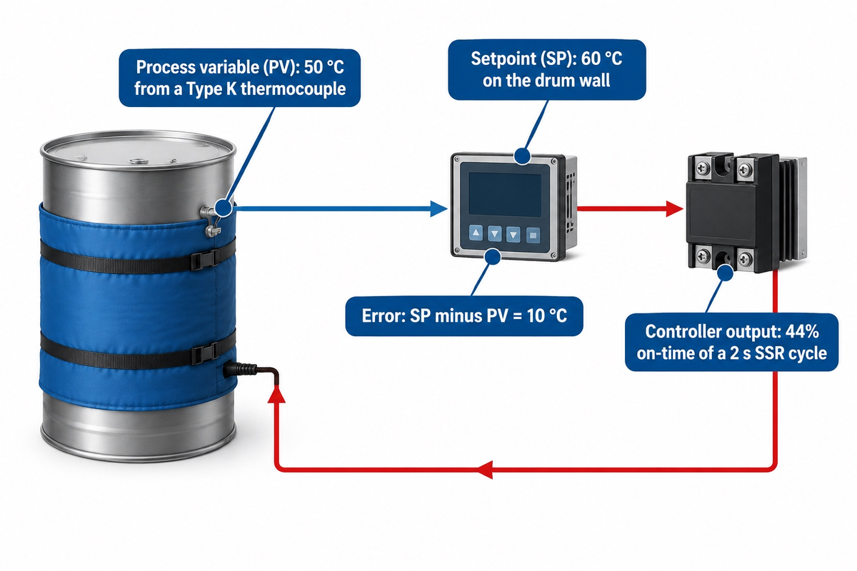
A PID controller is a closed-loop system element that reads a process variable from a sensor, subtracts it from the desired setpoint and sends a control signal to an output device. The proportional-integral-derivative controller is the most common industrial technology for closed-loop control, and ISA notes that it can be used to control temperature, pressure, flow and other process variables.
Every control process of this kind consists of a measurement, a decision and an actuator. The loop used to control a heated drum consists of four parts that can be pointed out: the temperature sensor clamped to the wall, the controller on the panel, the output device that switches power, and the heater itself. The controller calculates an error value every scan and then sends the output value to the solid-state relay or contactor. ISA’s Fundamentals of PID Control describes a similar loop on a steam water heater, where a sudden drop in hot-water demand, with the steam flow unchanged, makes the measured temperature rise like a first-order response with dead time.
| Term | Meaning | Heater example |
|---|---|---|
| Setpoint (SP) | Target value | 60 °C on the drum wall |
| Process variable (PV) | Measured value | 50 °C from a Type K thermocouple |
| Error | SP minus PV | 10 °C |
| Controller output (CO) | Command from zero to full output | 44% on-time of a 2 s SSR cycle |
Taking a PID control loop perspective, the controller changes the error signal into a control output between zero and full power. That control action repeats every scan, so the controller automatically takes care of a cold morning or a part-filled drum.
On/off thermostats measure and decide too, but their output has only two states: fully on below a lower threshold and fully off above an upper threshold, with hysteresis between them. A PID controller changes its output instead, so the heater can run at 30% or 60% of its rating while the drum holds a steady temperature.
What does PID stand for?
PID stands for proportional, integral and derivative, the three terms of PID that the controller adds together to set its output. Proportional controls react to the current error. Integral controls act on the accumulated error over time, and derivative controls act on the rate of change of the error. This gives an early indication of the future error. How a PID controller works on a heater follows from those names: each term acts on the heater output by its own amount, and the sum is transferred to the output device.
The principle of PID control predates electronic controllers. Nicolas Minorsky published the first formal analysis of three-term control in 1922 while studying automatic ship steering for the US Navy, according to the Wikipedia PID controller entry. Modern temperature controllers run the same principles in firmware, with a scan time of a fraction of a second, and the Wikipedia PID controller entry covers that history.
The PID Formula and What Each Term Does
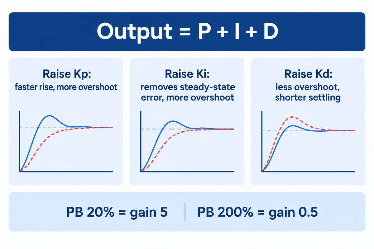
The PID formula in its parallel form is u(t) = Kp·e(t) + Ki·∫e(t) dt + Kd·de(t)/dt. Here, e is the error between the setpoint and the measured process variable. The standard form of an industrial controller is u = Kp[e + (1/Ti)∫e dt + Td·de/dt], where Ti and Td are in seconds.
The error is the difference between the setpoint and the measured value, and it’s the control input to the proportional and integral terms. Industrial controllers tend to take the derivative of the measured value, and so a setpoint change doesn’t kick the output. In control theory, the transfer function of the parallel form is Kp + Ki/s + Kd·s. The two forms yield the same output when Ki = Kp/Ti and Kd = Kp·Td. The standard form is more common in industry, and Ti and Td have a physical meaning: with a constant error, Ti is the time the integral contribution takes to grow by as much as the proportional contribution, and Td is how far ahead the derivative term looks. The standard PID form is the one most temperature controllers use, so the PID parameters on their menus are PB, Ti and Td. The University of Michigan control tutorial states what raising each gain does to the response.
| Raise | Rise time | Overshoot | Settling time | Steady-state error |
|---|---|---|---|---|
| Kp | Decrease | Increase | Small change | Decrease |
| Ki | Decrease | Increase | Increase | Decrease |
| Kd | Small change | Decrease | Decrease | No change |
Proportional control gives an output proportional to the error. A proportional controller alone provides an offset because some small error is needed to keep the heater on at all; ISA calls that residual error the offset. Integral action, or integral control, is the integrator that accumulates error until the offset is removed, and a PI controller removes the offset at steady state, as long as the heater can carry the load and the output isn’t pinned at its limit. Derivative control opposes fast changes and damps oscillation, which explains why the derivative component matters most on loops that overshoot.
Proportional band is where most heater users get confused. ISA’s list of tuning errors puts it plainly: “The gain setting is dimensionless and is 100 percent divided by the proportional band.” A PB of 20% means a proportional gain of 5; a PB of 200% means a gain of 0.5. Integral settings have the same trap, because one controller shows repeats per minute, and the other shows minutes per repeat, and a larger number means more integral action in the first controller, and less in the second.
The conversion holds when the setpoint, process variable and output are all scaled as percent of the instrument span. ISA’s 2023 review of the ISA-TR5.9-2023 PID technical report states that, in the parallel, standard and series forms, “PV, SP, and CO are assumed to be expressed in dimensionless values as percent of engineering unit (EU) range”. A controller with a 0–200 °C input range therefore treats a 10 °C error as 5%, not as 10.
What is the difference between P, PI and PID control?
P control uses only the current error and leaves an offset. PI control adds the integral term and removes the offset at steady state. PID control adds the derivative term to brake fast rises. In temperature control loops, plants that use PID usually run PI control with the derivative set to zero. This is because the sensor signal carries noise, and the derivative term reacts too strongly to small disturbances in it.
The ISA Mentor Program discussion of derivative action calls derivative “the least frequently used mode in the PID controller”. A PD controller, with no integral, shows up in motion control and robotics more than in heating. A heater on P or PD control settles a few degrees below the setpoint against a constant heat loss, and only the integral term closes that gap.
Worked Example: PID on a 1500 W Heating Blanket
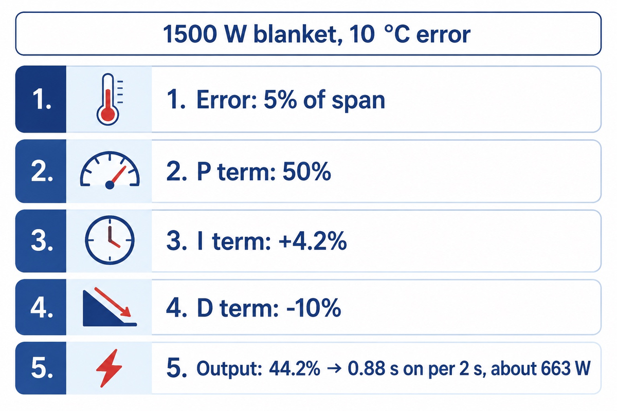
A 1500 W blanket running a PID controller at a 10 °C error ends up at about 44% output, or 0.88 s of on-time in each 2 s SSR cycle and roughly 660 W on average. The five lines below explain the calculation and how you can do the same with your setpoint.
5-Line Error-to-Watts Worksheet
The 5-Line Error-to-Watts Worksheet turns one controller scan into heater watts: error, P, I, D, then output and power.
Assumed inputs: a blanket rated 1500 W at 120 VAC drawing 12.5 A, the published rating of the FlexBlanket FLB-GTB-3010 ground thawing blanket (that model holds a fixed 70 °C face on its own, so treat this as a custom build wired to an external controller); controller input span 0–200 °C; setpoint 60 °C; measured 50 °C and rising at 0.05 °C/s; PB 10% (Kp 10); Ti 240 s; Td 40 s on measurement; integral starting at zero, 20 s after a cold start, with the error treated as constant over those 20 s (an approximation, since a rising temperature shrinks it); SSR cycle time 2 s.
| Line | Calculation | Result |
|---|---|---|
| 1. Error | (60 − 50) °C ÷ 200 °C span | 5% of span |
| 2. P term | 10 × 5% | 50% |
| 3. I term | 10 × (5% × 20 s) ÷ 240 s | +4.2% |
| 4. D term | −10 × 40 s × (0.05 °C/s ÷ 200 °C) | −10% |
| 5. Output and power | 50 + 4.2 − 10, clamped to 0–100%; × 1500 W | 44.2% → 0.88 s on per 2 s, about 663 W |
The PID output of 44.2% is what the SSR sees; how the actual system responds is a result of load heat losses. The arithmetic comes from the control algorithm, not a test result: a real world blanket also loses heat to the drum and air, so the measured curve is also load dependent. Double the error to 20 °C and the P term alone reaches 100%; with the same integral and derivative inputs the total comes to about 98%, and any larger error pins the output at its 100% limit, where the heater runs flat out at 12.5 A. A wider proportional band would make the system slower to reach setpoint but less likely to overshoot.
Integral windup starts at saturation. Once the output is pinned at 100%, the integral keeps adding error it’s unable to act on. Then, once the error reverses, the stored integral carries the drum past the setpoint. Some controllers have anti-reset windup functions that limit integration while the output is pinned. Check that it’s on before you raise the integral action on a large-mass load. A heater sizing worksheet sets the watts first, so the controller isn’t asked to make up for an undersized element.
PID vs On/Off Control for Heaters
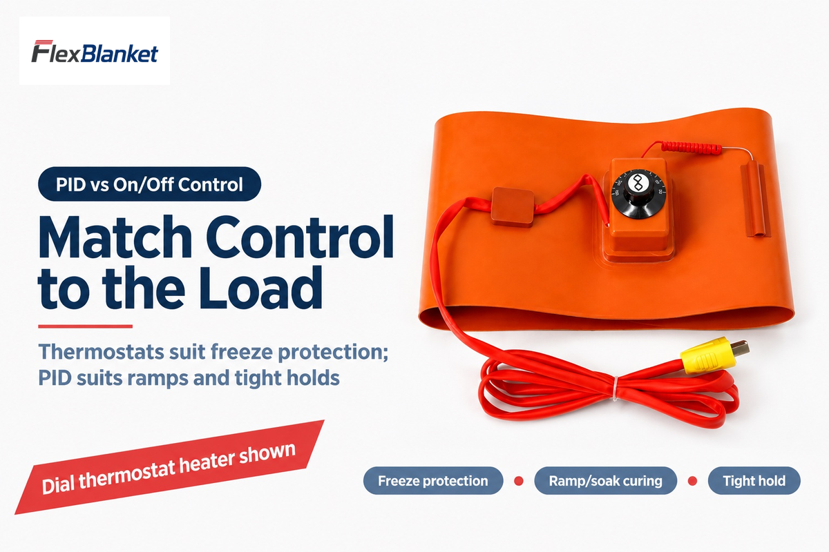
On/off control is adequate for freeze protection and general warming of large thermal masses. In one published heater test, it overshot less than a poorly sampled PID loop. PID is cost effective for heat-sensitive contents, ramped curing profiles, and other loops whose allowed swing is narrower than the deadband the on/off controller is set to.
Adonis and Khan compared both controllers on the same electric infrared heater for the Journal of Energy in Southern Africa in 2008. At a 1 s sampling period, overshoot at 100 °C was 8% with PID and 3% with on/off control, and the temperature offset at 220 °C was 8 °C against 4 °C, although PID had the shorter rise time from 100 °C to 220 °C (38 s against 57 s). At a 100 ms sampling period PID improved, with overshoot of 1% against 0% and an offset of 2 °C against 3 °C at 100 °C and 0 °C against 2 °C at 160 °C. The authors concluded that a simple on/off controller would be adequate for an industrial drying process.
Both types regulate temperature from the same sensor; they differ in how they control the temperature between switching points, and swapping a thermostat for a simple PID controller changes only how the heater is switched. On/off controllers need a deadband so the contactor doesn’t chatter. One 1/16 DIN controller manual specifies a default hysteresis of 2 °C and switches to on/off mode when its cycle time is set to zero. On/off controllers are used on FlexBlanket’s drum bands, which carry a 30–150 °C thermostat, and FlexBlanket suggests fixed-setpoint control for freeze protection duty, to cut cost, on its drum and IBC tote heaters, which cover 4 L pails to 1,250 L totes at working temperatures from −20 °C to 130 °C, and its silicone flexible heaters list a PID controller for “duties that need controlled ramp rates or tight holding around setpoint”.
| Duty | Typical heater | Control to start with | Move to PID when |
|---|---|---|---|
| Freeze protection of a 200 L drum | Drum band or jacket | Fixed-setpoint thermostat | Swing exceeds what the contents tolerate |
| Keeping oil or honey pourable | Drum band, 30–150 °C thermostat | Adjustable thermostat | The product is heat-sensitive |
| Warming a 1,250 L IBC tote | Tote jacket | Digital thermostat with display | Partly filled totes cycle the wall hot |
| Pipe viscosity control | Removable pipe jacket | On/off with a wide window | Restart load needs a ramp |
| Process temperature maintenance | Pipe jacket with RTD | PI controller | Add filtered derivative if sensor lag causes overshoot |
| Composite or epoxy curing | Multi-zone curing blanket | PID with ramp/soak | The cure schedule specifies ramp rates |
| Silicone heater, 1.0–3.0 W/cm² | Bonded silicone pad | PID with SSR | A ramp rate or tight hold is specified |
| Ground thawing and concrete curing | Fixed-face blanket, 70 °C | Built-in fixed regulation | Rarely; the face temperature is fixed |
| Drying with fast sampling | Infrared or plate heater | On/off | Offset matters more than 1% overshoot (100 ms sampling cut PID offset to 2 °C) |
When should you use a PID controller?
Use a PID controller when the contents tolerate less swing than the on/off deadband allows, when the heater must follow a ramp, or when the heater is powerful enough to overshoot a small load. For freeze protection and warming of a full 200 L drum, a fixed or adjustable thermostat holds temperature well enough at a fraction of the cost.
Budget approvals are the usual objection, so let’s put a number on the cost of overshoot: a scrapped batch of adhesive or a re-cured part can easily cost more than a $69.99 controller starter bundle. When the load is a large thermal mass and the allowed band is wide, keep the thermostat and spend the money on insulation.
PID Tuning Methods for Temperature Controllers
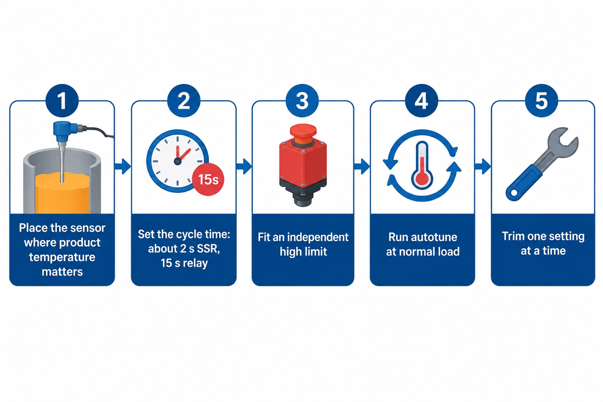
PID tuning for a heater starts with autotune at the normal setpoint and normal load, then corrects by hand: either widen the proportional band or lengthen the integral time if it overshoots, shorten the integral time if it sits below setpoint for minutes and narrow the proportional band if recovery after a load change is slow. Where a controller lacks autotune, the Ziegler-Nichols settings are a decent starting point, but for most heaters, they’re too aggressive.
Most technicians tune the PID loop of a heater in this order:
- Place the sensor: mount the temperature sensor where the product temperature matters, not in the air beside the heater.
- Set the cycle time: about 2 s for SSR outputs, 15 s or longer for mechanical relays.
- Fit the high limit: wire an independent over-temperature cutoff before the first autotune run.
- Run autotune: start from a stable temperature with the normal load in place and leave the setpoint alone until it finishes.
- Trim by symptom: change one setting at a time and wait at least one settling time before the next change.
Different tuning rules exist because loops differ: the appropriate PID settings for a thin silicone pad aren’t the same as for a 1,250 L tote. Autotune drives the heater through on/off cycles to measure the loop, so the first run can overshoot. Run it below the normal setpoint if 10 °C of overshoot would damage the load. The table below shows the manual tuning that follows, which is written for controllers that display the proportional band, integral time and derivative time.
| Symptom | Likely cause | Change |
|---|---|---|
| Overshoots, then settles | Integral too strong during warm-up | Lengthen Ti, for example 240 s to 360 s |
| Oscillates around setpoint | Gain too high | Widen PB, for example 10% to 15% |
| Sits a few degrees low | Integral off or too weak | Shorten Ti or turn integral on |
| Output jumps with sensor noise | Derivative amplifying noise | Set Td to 0 or add a derivative filter |
| Slow to recover after a load change | PB too wide | Narrow PB a step at a time, for example 15% to 12% |
| Overshoot only on cold starts | Integral windup at 100% output | Enable anti-reset windup or cutback |
The Ziegler–Nichols closed-loop method sets integral and derivative to zero, raises the gain until the loop oscillates steadily, and records that ultimate gain Ku and the oscillation period Tu. The Ziegler–Nichols table then gives Kp = 0.5 Ku for P only, Kp = 0.45 Ku with Ti = 0.83 Tu for PI, and Kp = 0.6 Ku, Ti = 0.5 Tu, Td = 0.125 Tu for classic PID. With Ku = 20 and Tu = 120 s, classic PID settings are Kp 12 (PB 8.3%), Ti 60 s and Td 15 s.
These numbers aim for a quarter wave decay, meaning each overshoot is a quarter of the one before it. ISA’s list of common tuning mistakes states the factors “provided overly aggressive control” in the original 1942 paper, so use them as an initial estimate and widen the proportional band if the first run overshoots. A successful PID tune shows one small overshoot and then holds; judgement of system performance is based on settling time and offset, not on how the first rise looks. Plants that tune PID controllers across hundreds of loops use tuning software, whereas a single heater zone rarely needs more than autotune and the symptom table.
Derivative needs special care on heaters. The sample environment team at NIST provides guidance on laboratory heater controllers and writes:
“The derivative term can be useful in fast changing systems but it is often turned off during steady state control because it reacts too strongly to small disturbances.”
The exception is sensor lag. ISA’s mentors provide the example of a thermowell with a 10 second time constant, and indicate that a derivative time of 10 seconds removes that lag. Derivative is recommended only if the controller has a filter on the derivative to strip high frequency noise. A thermocouple bonded to a silicone heater reads the heater face quickly, so PI is a reasonable first setting. Filtered derivative should be added to the controller only if the load itself also has lag.
Why does a PID controller overshoot the setpoint?
A PID controller overshoots because heat stored in the element and the load continues to raise the element temperature after the output drops, and because integral action built up during warm-up continues to push. A heater can only add heat, so after the temperature passes the setpoint, the controller can only switch off and wait for losses to cool the load.
The controller tries to stop the rise by cutting output, but stored heat keeps arriving. A sensor placed far from the heater makes this worse. The controller sees the rise and cuts power too late. FlexBlanket’s container heaters page names putting the sensor in the wrong place as the most common control mistake on a heated container. Moving a probe from the air gap to the drum wall shortens dead time and lets the same settings hold a tighter band.
Sensors and Outputs: Thermocouple, RTD, SSR or Relay
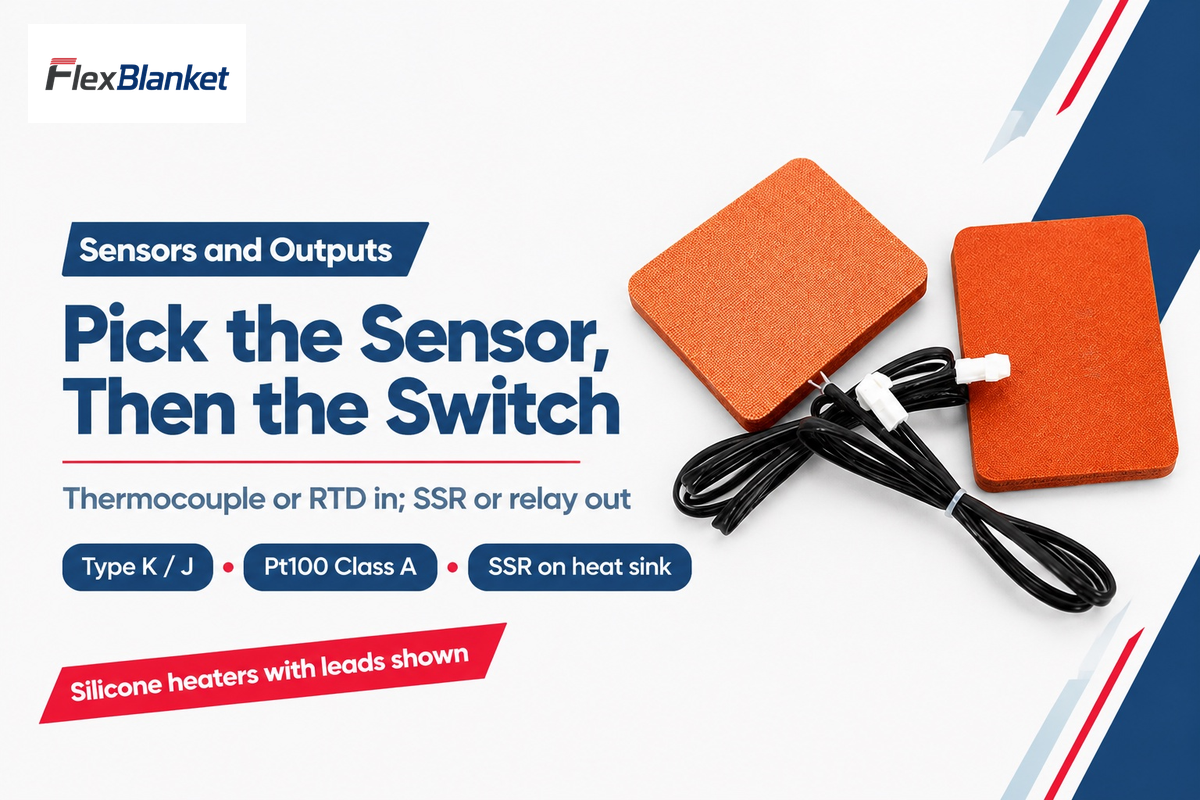
Many heater loops pair a Type K or Type J thermocouple, or a Pt100 RTD where the band is tight, with an SSR output switching every 1 to 2 seconds. Mechanical relays are suitable for slow loads, since their contacts can wear at faster cycle times. The sensor sets the accuracy of the loop, while the output device sets the fineness of heat delivery.
Thermocouple tolerances come from IEC 60584-1:2013, which specifies reference functions and tolerances for letter-designated thermocouples, and platinum RTDs from IEC 60751:2022, revised from the 2008 edition. The values in the matrix are the class tolerances as published by sensor suppliers that quote those standards.
| Option | Tolerance or timing | Best fit |
|---|---|---|
| Type K thermocouple, Class 1 | ±1.5 °C or ±0.004 × t | General heater loops to 1000 °C |
| Type K thermocouple, Class 2 | ±2.5 °C or ±0.0075 × t | Freeze protection, drum warming |
| Type J thermocouple, Class 2 | ±2.5 °C or ±0.0075 × t | Older controllers set for J input |
| Type T thermocouple, Class 1 | ±0.5 °C or ±0.004 × t | Low-temperature holding |
| Type T thermocouple, Class 2 | ±1.0 °C or ±0.0075 × t | Cold-weather tote warming |
| Pt100 RTD, Class A | ±0.15 °C at 0 °C | Process value to a written spec |
| Mechanical relay output | 15 s default cycle time | Large thermal mass, low switching rate |
| SSR drive (12 VDC pulse) | 2 s default cycle time | Blankets and silicone heaters |
| 4–20 mA analog output | Continuous signal | Power controllers and valves |
Cycle times are factory defaults from one manual for a 1/16 DIN controller and can be adjusted; other controllers allow a range from 0.1 second to 512 seconds. Short cycling on a mechanical relay creates contact wear, and practitioners on control forums trace hunting loops back to heat that could only be switched through a slow mechanical relay. An SSR can switch silently at 2 seconds, but requires a heat sink, which is why the eBay and Thermomart kits below ship each SSR with a heat sink.
The independent high limit is separate from all this. Cornell EHS’s Laboratory Safety Manual states “heating devices should have a backup power cutoff or temperature controllers to prevent overheating”, and FlexBlanket quotes a mechanical over-temperature switch, independent of the controller, as a separate scope item rather than a default on its process heating blankets. Give the limit its own sensor, so a failed thermocouple can’t blind both. The silicone heaters on FlexBlanket have a heating range of -60 °C to +250 °C with a uniformity of ±5 °C across the heated face. In those cases the sensor reads close to the surface temperature, within that ±5 °C band. The silicone rubber heaters guide gives an idea of where the sensor is located.
PID Controller vs PLC
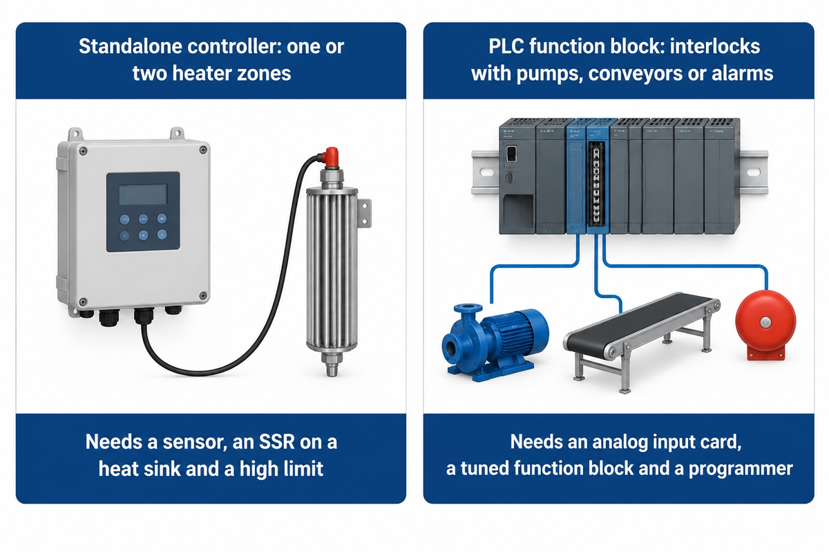
A PLC is a programmable controller that runs machine logic, and a PID is a control algorithm that can run within it or within a standalone panel controller. A standalone PID controller is sufficient for one or two heater zones; a PLC function block is warranted when the heaters must interlock with pumps, conveyors, or alarms that a PLC already controls. ISA’s temperature measurement and control fundamentals article is blunter: “if only temperature control is required, a DCS or a PLC is gross overkill.”
Plant engineers often object that adding a panel controller duplicates the PLC. The trade is wiring and commissioning time: a 1/16 DIN controller requires a sensor, an SSR on a heat sink and a separate high limit switch but no programming, while a PLC loop requires an analog input card, tuned function block and a programmer. Large plants move the loops to the distributed control system for remote control and trends; FlexBlanket offers a DCS output as a scope item on pipe heaters for that reason.
Applications of PID beyond heaters
Applications of PID include the speed of a motor, the position of a valve in a flow and pressure loop, level control, and cruise control. The control valve in a process plant is the most common final element; in industrial automation of a heater, it’s the SSR. The same formulae and tuning methods are applicable with different time constants, i.e. seconds for flow and minutes for a heated drum.
What a PID Temperature Controller Costs
A PID temperature controller kit with an SSR, heat sink and Type K thermocouple listed for US$18.29–24.49 on eBay in October 2026, and a Thermomart kiln kit with two SSRs and two heat sinks listed at 81.50 USD. The controller is the inexpensive part of a heater loop; the enclosure, high limit and wiring also add to it.
| Item | Listed price | What is included |
|---|---|---|
| REX-C100 type kit (eBay) | $18.29–24.49 | Controller, 40 A SSR, Type K thermocouple, heat sink |
| SSR-output starter bundle (Auber) | $69.99 | Controller, external SSR, K thermocouple |
| Kiln kit with 2 SSRs (Thermomart) | 81.50 USD | Controller, thermocouple, 2 SSRs, 2 heat sinks, 220 V |
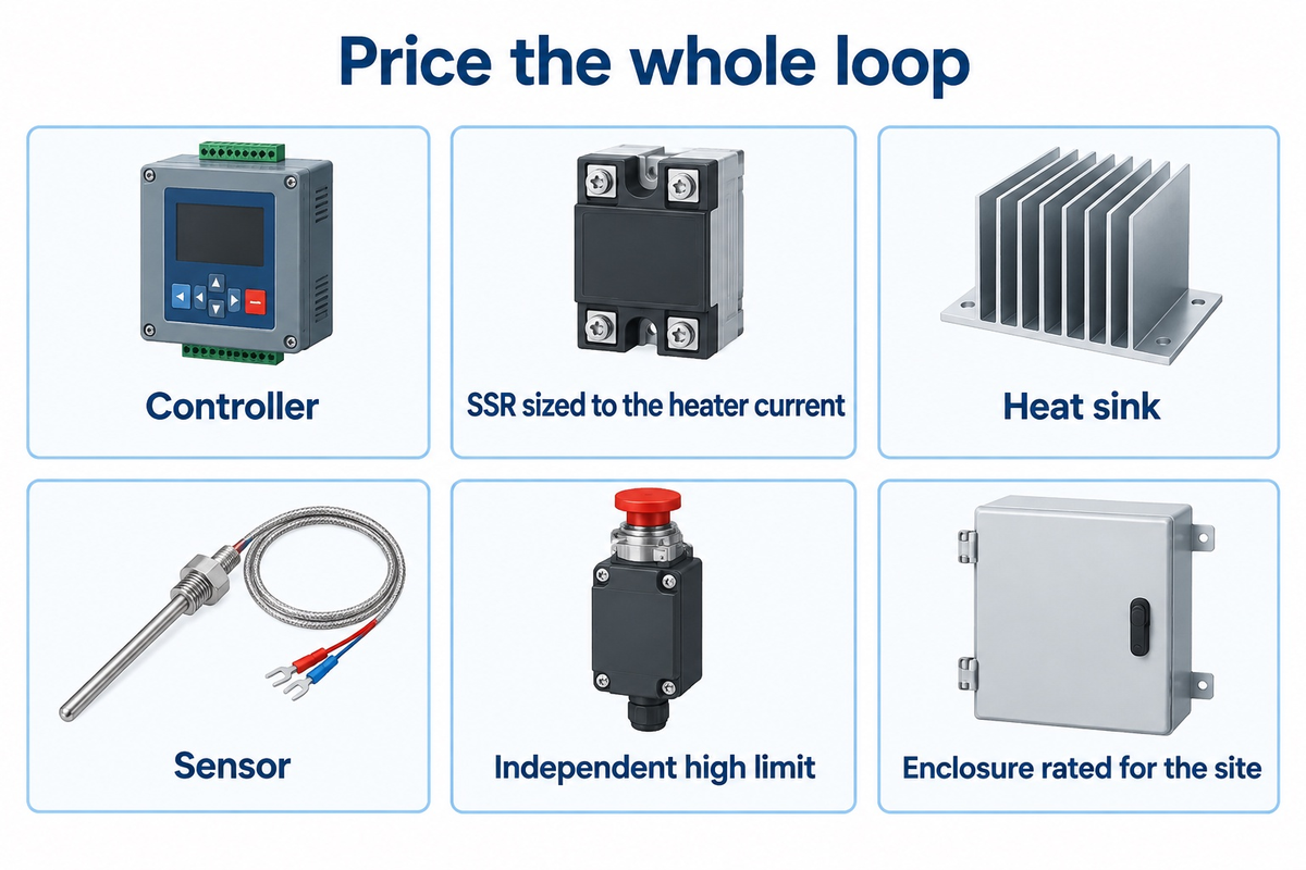
Industrial-brand panel controllers such as the Omron E5CC add 2-PID with auto-tuning, RTD, thermocouple and linear inputs, and three alarm relays in a 1/16 DIN case, which is what a plant buying for a written specification pays for. For a heating blanket, price the whole loop: controller, SSR sized to the heater current, heat sink, sensor, independent high limit and enclosure rated for the site. A 12.5 A, 120 VAC blanket fixes the circuit, so check the voltage and plug before ordering the controller.
Choosing a PID Controller for an Industrial Heater
For an industrial heater, a PID controller would require that sensor and supply be matched, that the SSR be sized above the load current, and that over-temperature protection be provided by another device. Those three choices, plus whether the loop requires a ramp or remote setpoint, would dictate the controller choice before any brand comparison. For the wider controller choice on heating blankets, including thermostats, wiring, voltage and alarms, see FlexBlanket’s temperature controller guide for heating blankets.
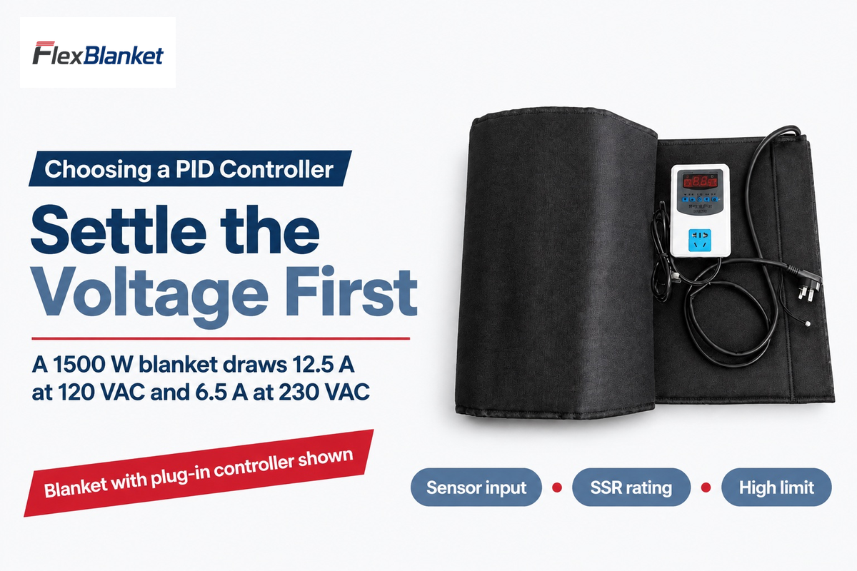
Site supply is the step that delays orders: the 120 VAC version of a 1500 W blanket draws 12.5 A and the 230 VAC version draws 6.5 A, so FlexBlanket’s planning rule is one blanket per 20 A circuit at 120 VAC, leaving headroom, and two at 230 VAC. Decide the voltage first, and then determine the SSR and wire gauge. FlexBlanket lists PID temperature control, current and temperature monitoring and the mechanical over-temperature switch as separate scope items on its pipe heaters, and builds custom heating blankets from a drawing, measured sketch or photographs of the heated equipment. Its pipe heating blankets rate the core at 220 °C for silicone, 300 °C for stitched and 400 °C for high-silica construction, so set the controller’s input range and the high-limit trip below the core limit of the build you order. The pipe process heating control guide goes further into monitoring.
RFQ checklist: copy these lines into the controller part of your quote request.
| Parameter | Recommended range | Why it matters | How to verify |
|---|---|---|---|
| Sensor input | Type K or J thermocouple; Pt100 Class A where the band is tighter than Class 1 thermocouple tolerance | Sets measurement tolerance | Input type on the controller label matches the heater sensor |
| Output type | 12 VDC SSR drive for blankets; relay only with a long cycle time set for contact life | Contact wear and band width | Cycle time setting in the manual |
| SSR rating | Rated above the heater current, mounted on a heat sink | A 1500 W blanket draws 12.5 A at 120 VAC | SSR datasheet current rating and sink size |
| Control mode | PI or PID with autotune; ramp/soak for curing | Overshoot and profile following | Autotune and program menus present |
| High limit | Independent device with its own sensor | Cuts power if the main loop fails | Wiring diagram shows separate sensor |
| Supply and comms | 120 or 230 VAC; RS-485 or 4–20 mA if a DCS reads it | Circuit size and remote setpoint | Supply on the nameplate; comms option code |
Ask for the control scope to be itemized on the quotation, line by line, to show whether the controller, sensor, high limit and enclosure are included, or left to the site electrician.
Frequently Asked Questions
Q: Is a PID controller hardware or software?
A PID controller can be either: a standalone hardware unit on a panel, or a software function block inside a PLC or DCS.
Both run the same algorithm on a scan cycle. A 1/16 DIN hardware controller is the usual choice for one heater zone because it needs no programming, while a software loop suits plants that already log and alarm through a PLC.
Q: Are PID controllers still used?
Yes. PID remains the most common industrial technology for closed-loop control, according to ISA, more than a century after the first PID-type controllers.
Newer tools, including AI tuning assistants, recommend gain changes in the background, but the PID loop still does the controlling on heaters, valves and motors. ISA published its ISA-TR5.9-2023 technical report on PID algorithms as groundwork for a standard.
Q: Is a PID controller closed loop?
Yes. A PID controller is closed loop because it measures the process variable and corrects its output from the error every scan.
An open-loop heater timer switches power on a schedule without measuring anything, so it can’t correct for a cold morning or a part-filled drum. Remove the sensor and a PID controller loses its feedback entirely.
Q: What is a PI controller?
A PI controller is a PID controller with the derivative term set to zero.
Proportional and integral action remove the steady offset without the noise sensitivity of the derivative term, which is why PI is a common default on temperature loops.
Q: How does a PID temperature controller work with an SSR?
The controller turns its 0–100% output into on-time within a fixed cycle, and the SSR switches the heater on for that share of each cycle.
At a 2 s cycle, 25% output means 0.5 s on and 1.5 s off, so a 1500 W heater delivers about 375 W on average. The controller sends a 12 VDC drive signal; the SSR switches the 120 or 230 VAC heater current. Size the SSR above the heater current and mount it on a heat sink, because it runs warm while conducting.
Q: What does Kp mean on a temperature controller?
Kp is the proportional gain, the output change per unit of error.
Many controllers show proportional band instead; when error and output are both in percent of span, PB in percent equals 100 divided by Kp, so PB 10% is a gain of 10.
Q: Can one PID controller handle heating and cooling?
Yes, if it has a heating-cooling control mode and a second control output, not just an alarm relay, to drive a fan, valve or chiller above setpoint.
Heating-cooling models carry a separate proportional band for the cooling side, because a fan removes heat at a different rate than the heater adds it. On a heating blanket the second output is rarely needed, since the load cools on its own; it earns its place on extruders and processes that release heat as they run.
About This Analysis
FlexBlanket builds removable heating blankets, drum and tote heaters and silicone heaters, and this guide covers which PID controller settings fit those heaters. The worked example uses our FLB-GTB-3010 rating; the comparison data comes from ISA, NIST and a peer-reviewed heater test.
References & Sources
- Fundamentals of PID Control, International Society of Automation, InTech, June 2023
- PID controller, Wikipedia
- Introduction: PID Controller Design, University of Michigan, Control Tutorials for MATLAB and Simulink
- ISA-TR5.9-2023: Realizing and Achieving Best PID, International Society of Automation, InTech
- When and How to Use Derivative Action in a PID Controller, ISA Mentor Program
- Temperature Measurement and Control Fundamentals, International Society of Automation, InTech, August 2023
- Analysis of the efficacy of a simplified infrared energy management system, Adonis and Khan, Journal of Energy in Southern Africa 19(2), 2008
- Ziegler–Nichols method, Wikipedia
- How to Avoid Common Tuning Mistakes With PID Controllers, International Society of Automation
- PID Temperature Control, NIST Center for Neutron Research
- IEC 60584-1:2013 Thermocouples, EMF specifications and tolerances, International Electrotechnical Commission
- IEC 60751:2022 Industrial platinum resistance thermometers and platinum temperature sensors, International Electrotechnical Commission
- Laboratory Safety Manual, Section 16.6, Cornell University Environment, Health and Safety